Billy Goat BC26 Operator's Manual
Hide thumbs
Also See for BC26:
- Operator's manual (21 pages) ,
- Owner's manual (20 pages) ,
- Owner's manual (20 pages)
Table of Contents
Advertisement
Quick Links
Advertisement
Table of Contents

Related Manuals for Billy Goat BC26


Summary of Contents for Billy Goat BC26
- Page 1 BC26 Operator's Manual Beginning Serial #: 031523001 Models BC2600ICH BC2600ICHC BC2600ICHFT BC2600ICM BC2601HH BC2601HHC BC2601HHFT BC2601HEBH BC2601 HEBHFT BC2601HM BC2601HMFT Original Instructions IMPORTANT- READ CAREFULLY BEFORE USE AND KEEP FOR FUTURE REFERENCE 501530 C...
-
Page 2: Table Of Contents
Table of Contents: Identifying Your Unit............3 Intended Use................. 3 Initial Setup................3 Installing the Handle Assembly........3 Installing the Front Guard Bar..........4 General Setup..............4 Features and Controls............5 Engine Pull Starter............5 Engine Electric Starter............5 Throttle Lever..............5 Drive Handle..............5 Direction Shifter.............. -
Page 3: Identifying Your Unit
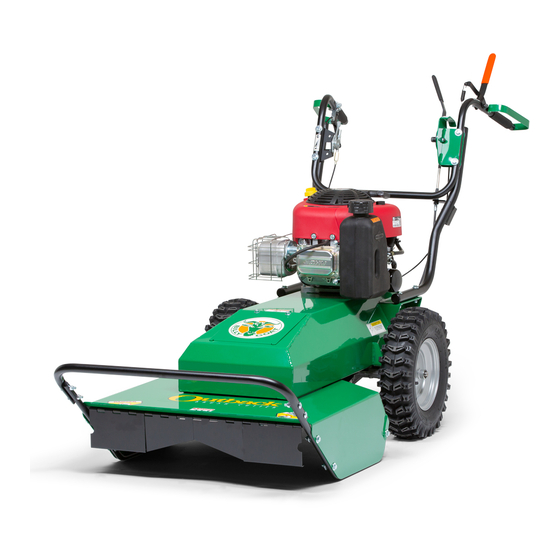
Identifying Your Unit sure that all operators of this equipment are trained in general machine use and safety. Thank you for purchasing this quality piece of outdoor power equipment. Before operation, please note the Initial Setup product Identification Tag (A, Figure 1) which is found at the operator's position, below the handlebars. -
Page 4: Installing The Front Guard Bar
2. Install the front guard bar onto the front left and right skid bars (B). Use the bolts (C), washers (D), and nuts (E) to secure the guard bar to the skid bars. General Setup Your unit was shipped in a box or wooden crate. Remove the unit from the carton and remove all packaging. -
Page 5: Features And Controls
Features and Controls Engine Pull Starter Note: Check engine oil and fuel levels before attempting to start the engine! Add oil and/or fuel, if necessary. Fits: Non-Electric Units. Pull the starter rope to start the engine. Pull the starter cord slowly until resistance is felt. Then, pull the cord rapidly to avoid kickback. -
Page 6: Direction Shifter
Direction Shifter Fits: Mechanical drive models The direction shifter allows the operator to change drive direction and gear. Reference the direction shifter decal (Figure 9) to select from reverse, neutral, or forward motion. Forward motion provides first, second, or third gear options. To select direction, move the direction shifter lever up or down. -
Page 7: Reverse Handle
Free Wheel Lever Fits: Hydro-drive models Use the Free Wheel Lever (A, Figure 14) to push the unit by hand. Pull out the lever to disengage drive-enabled motion. This will allow you to transport and push the unit by hand. Push the lever in to engage drive-enabled motion. - Page 8 billygoat.com...
-
Page 9: Operation
Operation 2. Shut down the unit. Mechanical-drive models can now be pushed by hand. 3. Hydro-Drive models: Locate the free wheel lever. See Starting the Engine the Free Wheel Lever section for more information. Pull out the free wheel lever to disengage the transaxle. You will now be able to push hydro-drive models unit by hand. -
Page 10: Maintenance Procedures
Maintenance Procedures Clearing a Clogged Deck DANGER The blade is sharp! To avoid injury, always wear heavy- duty gloves when performing maintenance on the cutting deck. 1. Park the unit on a flat, level surface. Turn off the engine and disconnect the spark plug wire. 2. -
Page 11: Replacing The Blade
Replacing the Blade 1. Park the unit on a flat, level surface. Turn off the engine and disconnect the spark plug wire. DANGER 2. Safely lift and support the unit to allow access to the The blade is sharp! To avoid injury, always wear heavy- underside of the unit. -
Page 12: Replacing The Drive Belt
5. Walk the drive belt (A) off of the clutch (D). 4. To release the tension on the drive belt (A, Figure 24), detach the drive belt spring (B) from the spring bolt (C). Figure 24 displays the drive system when viewed from CAUTION below. -
Page 13: Adjusting Drive Cable Tension
Adjusting Drive Cable Tension Fits: Mechanical-drive models. CAUTION The belt and clutch can create a pinch-point. Use caution 1. Park the unit on a flat, level surface. Turn off the engine when performing maintenance. and disconnect the spark plug wire. 2. -
Page 14: Replacing The Blade Belt
2. Refer to the Replacing the Drive Belt section to remove the drive belt. 3. Remove the deck cover (A, Figure 27). Loosen and remove the four screws (B) that secure the deck cover, and then remove the deck cover. 5. With blade belt tension relieved, walk the blade belt (A) off of the blade pulley (C). -
Page 15: Adjusting The Blade Belt Tension
7. Install a new blade belt. First, install the blade belt onto the clutch. Then install the blade belt onto the idler pulley and blade pulley. Reinstall the blade extension spring. Reinstall the deck cover. 8. Reinstall the drive belt. Reinstall the lower belt guard. Reconnect the spark plug wire. -
Page 16: Battery Care
4. Inspect the condition of the belt (B, Figure 33). Replace the blade belt if worn or damaged. See Replacing the Blade Belt for more information. 5. Reinstall the deck cover. See Step 2. 6. Reconnect the spark plug wire. 7. -
Page 17: Periodic Maintenance
Periodic Maintenance Maintenance Every Use Every 25 Hrs Every 50 Hrs Every 100 Hrs Operation Inspect for worn or damaged parts. Check for excessive vibration. X Inspect for loose parts. Sharpen the blade. Inspect belts for wear. Lubricate throttle control cable and linkage. -
Page 18: Specifications
Problem Possible Cause Corrective Action Engine will not turn over. Defective blade clutch. Replace clutch. Engine problem. Contact an authorized servicing dealer for your engine. Specifications Height: 48" (1.22 m) Briggs and Stratton Fits Units: BC2601HEBH BC2601HEBHFT Fits Units: BC2600ICH Length: 83"...
Need help?
Do you have a question about the BC26 and is the answer not in the manual?
Questions and answers