
Related Manuals for Billy Goat HYDRO-DRIVE BC2601HHFT


Summary of Contents for Billy Goat HYDRO-DRIVE BC2601HHFT
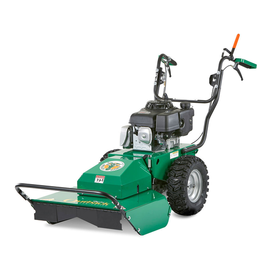
- Page 1 BC26 HYDRO-DRIVE Operator’s Manual BC2601 Hydro-Drive Series Brush Cutter Operator’s Manual Beginning Serial #: 122020001 Original Instructions IMPORTANT- READ CAREFULLY BEFORE USE AND KEEP FOR FUTURE REFERENCE Part No 501530 501530_B_HI...
-
Page 2: Table Of Contents
BC26 HYDRO-DRIVE Operator’s Manual CONTENTS SPECIFICATIONS AND SAFETY __________ INSTRUCTION LABELS ASSEMBLY INSTRUCTIONS OPERATION MAINTENANCE AND BATTERY MAINTENANCE 10-13 TROUBLESHOOTING ILLUSTRATED PARTS LIST 15-22 Go to http://www.billygoat.com for French-Canadian translations of the product manuals. Visitez http://www.billygoat.com pour la version canadienne-française des manuels de produits Part No 501530 501530_B_HI... -
Page 3: Specifications And Safety
BC26 HYDRO-DRIVE Operator’s Manual SPECIFICATIONS BC2601HHFT BC2601HH BC2601HEBH BC2601HEBHFT Engine Type Honda GXV390 Honda GXV390 Honda GXV390 Honda GXV390 Model Number GXV390UT1 DABG GXV390UT1 DABG GXV390UT1 DE33 GXV390UT1 DE33 Displacement 390 cc 390 cc 390 cc 390 cc Fuel Capacity 2.2 qt (2.1 L) 2.2 qt (2.1 L) 2.2 qt (2.1 L) -
Page 4: Instruction Labels
INSTRUCTION LABELS ® The labels shown below were installed on your BILLY GOAT Hydro-Drive Brush Cutter. If any labels are damaged or missing, replace them before operating this equipment. Item numbers from the Illustrated Parts List and part numbers are provided for convenience in ordering replacement labels. -
Page 5: Assembly Instructions
BC26 HYDRO-DRIVE Operator’s Manual Brush Cutter Assembly Drawing Part No 501530 501530_B_HI... - Page 6 PACKING CHECKLIST ® Your BILLY GOAT BC Self-Propelled Hydro-Drive Brush Cutter was shipped in one carton, completely assembled except for the upper handle assembly and the front guard bar. Mounting hardware for the handle and guard bar is temporarily installed on the lower handle and the front of the deck assembly.
-
Page 7: Operation
BC26 HYDRO-DRIVE Operator’s Manual spark plug wire. 10. RECONNECT OPERATION OPERATOR CONTROLS The operator’s station is at the rear of the machine between the handlebars. The operator should STAND in a position to allow both handlebars to be grasped firmly and which allows sufficient leverage to steer the machine. Operator’s controls are shown below. - Page 8 BC26 HYDRO-DRIVE Operator’s Manual CUTTING OPERATION 1. Press blade clutch handle down (See Fig. 5) to engage blade. Allow blade to spin up to normal operating speed. 2. Pull Forward (See Fig. 6) or Reverse Drive lever (See Fig. 7) up to engage transaxle in desired direction.
- Page 9 • ® Your BILLY GOAT Brush Cutter should be cleaned periodically to ensure optimum performance and service life. Clogs and debris should be removed from the blade area and debris should be removed from the engine cooling fins. A garden hose or pressure washer may be used for cleaning.
-
Page 10: Maintenance And Battery Maintenance
4. Remove blade bolt (item 23), and friction washer (item 39). 5. Remove blade (item 2) and install replacement blade. When replacing the blade, only use BILLY GOAT Industries PN 501224. NOTE: When sharpening blade make sure to sharpen all cutting edges. If the lock nut is removed and replaced more than once, it should be replaced with a new lock nut (P/N 8160009). - Page 11 BC26 HYDRO-DRIVE Operator’s Manual NOTE: See Fig 12 for proper belt routing. TRANSAXLE DRIVE BELT REMOVAL AND REPLACEMENT (See pages 21 and 22 for Parts Illustration and Parts List) DISCONNECT spark plug wire before servicing unit. 1. Disconnect spark plug wire. 2.
- Page 12 BC26 HYDRO-DRIVE Operator’s Manual 1. Disconnect spark plug wire. INCREASE 2. Adjustments to cable tension are made at the barrel entering the Drive Control Levers. (See Fig. 13) 3. Adjust cable tension by tightening or loosening cable adjustment barrel on rear of engine base (see below). DECREASE NOTE: Moving the cable adjustment barrel OUT increases tension.
- Page 13 BC26 HYDRO-DRIVE Operator’s Manual • Do not allow the battery charge to get too low. If the machine is not used, charge the battery every 4 – 6 weeks. Operate the engine for at least 45 minutes to maintain proper battery charge. •...
-
Page 14: Troubleshooting
BC26 HYDRO-DRIVE Operator’s Manual TROUBLESHOOTING Problem Possible Cause Corrective Action Engine will not start Throttle is set to Slow/Stop position. Move throttle to fast position. Out of gasoline. Fill gas tank. Old or contaminated gasoline. Drain gas tank and fill with fresh gasoline. -
Page 15: Illustrated Parts List
BC26 HYDRO-DRIVE Operator’s Manual BC26 HYDRO-DRIVE DECK PARTS DRAWING Note: Item No. 169 includes: • Item No. 44 • Item No. 20 • Billy Goat Part No. 501101 Part No 501530 501530_B_HI... - Page 16 BC26 HYDRO-DRIVE Operator’s Manual BC26 HYDRO-DRIVE DECK PARTS LIST ITEM BC2601HEBH BC2601HEBHFT BC2601HH BC2601HHFT DESCRIPTION SCREWCAP 3/8-24 X 1” HCS GR. 8 900154 900154 900154 900154 BLADE 26” FLAT BC26 501224 501224 501224 501224 WASHER DECK RETAINNG 501214 501214 501214 501214 LABEL BADGING BC26 HYDRO 501500...
- Page 17 BC26 HYDRO-DRIVE Operator’s Manual BC26 HYDRO-DRIVE ENGINE PARTS DRAWING Part No 501530 501530_B_HI...
- Page 18 BC26 HYDRO-DRIVE Operator’s Manual BC26 HYDRO-DRIVE ENGINE PARTS LIST BC2601HHFT ITEM BC2601HEBH BC2601HEBHFT BC2601HH DESCRIPTION SCREWCAP 3/8-24 X 1” HCS 900154 900154 900154 900154 GR. 8 WASHER DECK RETAINING 501214 501214 501214 501214 NUT LOCK 5/16”-18 ZP 8160002 8160002 8160002 8160002 ENGINE BASE WA 501603...
- Page 19 BC26 HYDRO-DRIVE Operator’s Manual BC26 HYDRO-DRIVE HANDLE PARTS DRAWING Part No 501530 501530_B_HI...
- Page 20 BC26 HYDRO-DRIVE Operator’s Manual BC26 HYDRO-DRIVE HANDLE PARTS LIST ITEM BC2601HEBH BC2601HEBHFT BC2601HH BC2601HHFT DESCRIPTION NUT LOCK 5/16-18 ZP 8160002 8160002 8160002 8160002 NUT LOCK 3/8-16 HEX 8160003 8160003 8160003 8160003 HANDLE LOWER LEFT 501400-P 501400-P 501400-P 501400-P BRACKET THROTTLE BC26 501251 501251 501251...
- Page 21 BC26 HYDRO-DRIVE Operator’s Manual BC26 HYDRO-DRIVE TRANS PARTS DRAWING Part No 501530 501530_B_HI...
- Page 22 BC26 HYDRO-DRIVE Operator’s Manual BC26 HYDRO-DRIVE TRANS PARTS LIST BC2601HHFT ITEM BC2601HEBH BC2601HEBHFT BC2601HH DESCRIPTION NUT LOCK 1/4”-20 HEX ZP 8160001 8160001 8160001 8160001 NUT LOCK 5/16”-18 8160002 8160002 8160002 8160002 ENGINE BASE WA W/LABELS 501603 501603 501603 501603 SCREW SELT TAP 1/4-20 X 5/8” 890359 890359 890359...
- Page 23 BC26 HYDRO-DRIVE Operator’s Manual CABLE SPEED CONTROL LFT 351271-S 351271-S 351271-S 351271-S SERVICE LABEL DRIVE RELEASE 501504 501504 501504 501504 LABEL CHOCK WHEELS 500168 500168 500168 500168 SPRING IDLER BC 501261 501261 501261 501261 SPRING PIN CONTROL ROD 501262 501262 501262 501262 SPHERICAL ROD END MSF-5...
Need help?
Do you have a question about the HYDRO-DRIVE BC2601HHFT and is the answer not in the manual?
Questions and answers