Table of Contents
Advertisement
Quick Links
T
P
HE
O
PERATING AND
ENGINE: H.P.
ENGINE: TYPE
ENGINE: CAPACITY
ENGINE: FUEL CAP.
ENGINE: OIL CAP.
WEIGHT: UNIT
MAX. ENGINE OPERATING SLOPE:
UNIT SIZE:
370310
T
Y
HANK
OU FOR
B
G
OWERFUL
ILLY
S
AFETY
M
: SC120H
ODEL
S
PECIFICATIONS
5.5 (4.1 KW)
Gasoline, HONDA GX 160 K1
5.5 hp (4.0 kW)
3.0 qt. (2.84L)
0.66 qt. (0.6 L)
160.9 # (73 Kg)
15°
30.7 in x 16.5 in x 24.0 in (0.78 m x 0.42 m x 0.61 m)
1
S
ELECTING
S
C
OAT
OD
UTTER
I
NSTRUCTIONS
F112003A
Advertisement
Table of Contents

Related Manuals for Billy Goat SC120H


Summary of Contents for Billy Goat SC120H
- Page 1 MAX. ENGINE OPERATING SLOPE: UNIT SIZE: 370310 OU FOR ELECTING ILLY UTTER AFETY NSTRUCTIONS : SC120H ODEL PECIFICATIONS 5.5 (4.1 KW) Gasoline, HONDA GX 160 K1 5.5 hp (4.0 kW) 3.0 qt. (2.84L) 0.66 qt. (0.6 L) 160.9 # (73 Kg) 15°...
-
Page 2: Operating And Safety Instructions
PERATING AND AFETY NSTRUCTIONS SOD CUTTER MODEL-SC120H FOREWORD This machine may only be utilized for the purpose for which it was designed, i.e. agricultural use, for the cutting of shoots, grass and brushwood. Any other use other than that stated, not covered or deducible from this Manual and the enclosed Engine Manual is "PROHIBITED". - Page 3 Contents of the SOD CUTTER Manual Use of the Manual Notices on the machine Technical data Lifting and transportation Main parts of the machine Controls and adjustments Assembly instructions for the handlebars and end part of the cutting height adjustment lever Safety information a) General instructions b) Training...
-
Page 4: Notices On The Machine
2. N OTICES ON THE MACHINE In this Manual all safety information appears in special boxes headed "WARNING". This heading is used to draw the user's attention to hazardous areas or moving parts of the machine. It is also used in instances where failure to comply with the instructions given may result in injury to persons and animals or damage to property. - Page 5 370302 – Label Controls Instruction, Qty. 1 370300 – Label Instructions, Qty. 1 SC120H ECHNICAL ATA FOR THE UTTER 370310 F112003A...
- Page 6 ENGINE ENGINE CAPACITY CUTTING WIDTH CUTTING HEIGHT SPEED GEARS TRANSMISSION GEARS START HEIGHT-ADJUSTABLE HANDLEBARS TIRES front tires DIMENSIONS L x W x H (mm) WEIGHT (kg) ACOUSTIC PRESSURE, measured according to ACOUSTIC POWER, measured according to VIBRATION LEVEL TRANSMITTED TO THE HANDLEBAR Environmental conditions Unless otherwise stated at the time of ordering it is understood that the machine is to work normally in the environmental conditions covered by the following points.
- Page 7 All material is carefully checked by the manufacturer before shipping. The sod cutter is delivered in a cardboard box with the handlebars and end part of the cutting height adjustment lever disassembled. Upon receipt of the machine make sure that it has not been damaged during transit and that the packaging has not been tampered or any parts removed.
-
Page 8: Main Parts Of The Machine
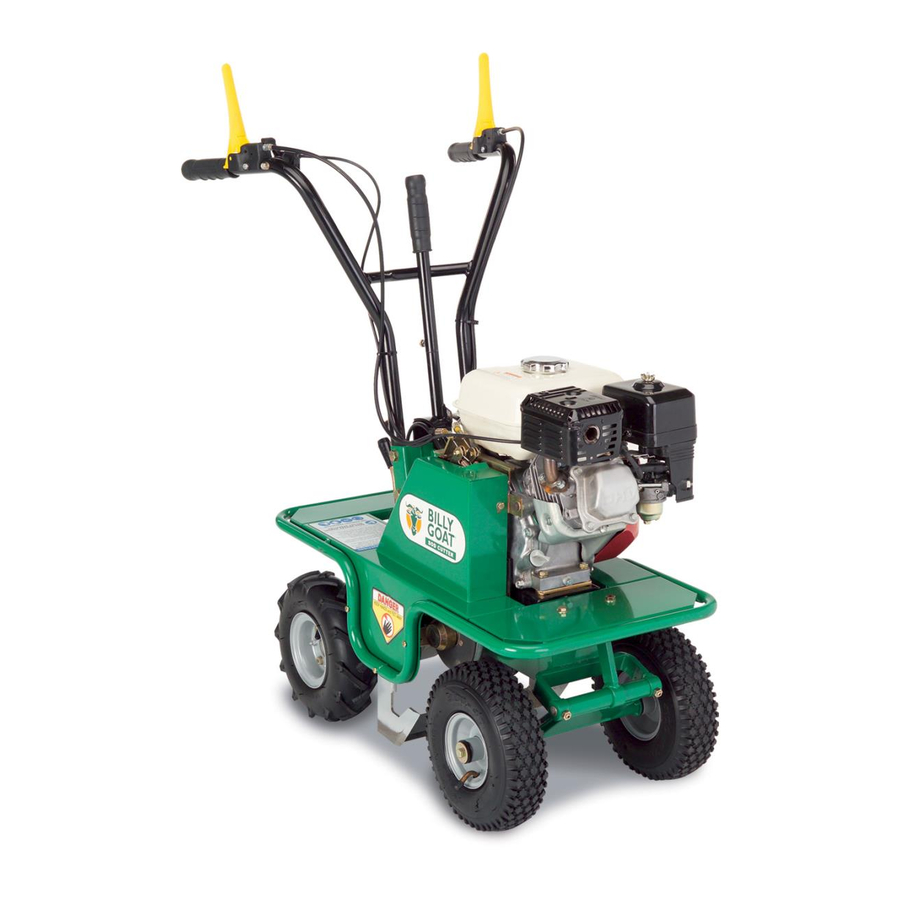
AIN PARTS OF THE MACHINE The machine consists of the following main parts – Blade clutch control lever – Accelerator control lever – Forward clutch control lever – Cutting height adjustment lever – GX 160 K1 engine – Cover – Blade –... -
Page 9: Control And Adjustments
ONTROL AND DJUSTMENTS BLADE CLUTCH CONTROL LEVER This is used to engage and disengage the blade movement. Lowering the lever engages the clutch and releasing it disengages the clutch. WARNING The blade will continue to move if the engine is running and the blade clutch is engaged, regardless of the position of the forward clutch. -
Page 10: Cutting Height Adjustment Lever
D) CUTTING HEIGHT ADJUSTMENT LEVER This lever serves to adjust the cutting height according to the type of terrain and the thickness of the turf to be cut. (Fig.2 Ref. A) F) COVER The cover ( Fig. 1, ref. F) prevents any contact with the moving parts of the machine. - Page 11 6. A SSEMBLY INSTRUCTIONS FOR THE HANDLEBARS AND END PART OF THE CUTTING HEIGHT ADJUSTMENT LEVER The sod cutter is delivered with the handlebars and the end part of the cutting height adjustment lever disassembled. Remove the cardboard packaging (to be disposed of in an appropriate manner, in accordance with current regulations in force).
-
Page 12: Safety Information
AFETY INFORMATION Before using the sod cutter it is essential that the operator has understood the warnings, do's and don'ts and precautionary measures given in this manual and in the engine manual: the prevention of injury to the operator, third parties, animals or objects directly depends on observance of these instructions. - Page 13 ! Supervise the clothing of personnel operating the machine: a long-sleeved jacket with close-fitting cuffs, long, close-fitting trousers, heavy-duty footwear, and a protective cap or helmet should be worn. Avoid wearing loose-tailed clothing, unbuttoned jackets or torn, undone or partially zipped up items to pre- vent them from being caught up in the moving parts.
-
Page 14: After Use
WARNING. When working in a stony or obstacle-riddled area try to remove as many objects as possible before commencing cutting. Then work at a greater cut- ting height than usual. WARNING Stones and other objects may be thrown outwards in direction of the opera- tor or of other persons in the vicinity. -
Page 15: Transportation Of The Machine
RANSPORTATION OF THE MACHINE OADING AND UNLOADING FROM A VEHICLE ! For transportation it is preferable to use a vehicle with an open bed. ! Choose firm, flat ground. Switch off the vehicle's ignition, put into reverse gear, pull on the hand brake and block the tires with chocks to prevent accidental movement of the vehicle. -
Page 16: Operations To Be Carried Out Before Switching On
10. D ESCRIPTION OF THE SAFETY AND GUARD SYSTEMS WARNING The safety devices must never be tampered with. It is necessary to understand how they work and safeguard their efficiency and correct operation. In the instance of doubt, prob- lems or malfunction contact your dealer. FORWARD CONTROL AND BLADE MOVEMENT LEVERS When released both of these levers instantly disengage the transmission con- nected to them. - Page 17 12. S TARTING AND DRIVING THE SOD CUTTER The machine can be switched on once all the aforementioned preliminary opera- tions have been carried out. Place the feed cock in the OPEN position (direction shown by the arrow) (fig. 4) Bring the choke to the CLOSED position for a cold start (direction shown by the ar- row, Fig.
-
Page 18: Driving The Machine
RIVING THE MACHINE WARNING. When using the machine for the first time it is advisable to get the feel of it by executing manoeuvres on flat ground free of foreign objects. After switching on the engine following the instructions given in the previous para- graph: 1. - Page 19 HECKS Adjust the belt and cable control tension after the first few working hours to compensate initial loosening. Briefly operate all the machine's components to detect any abnormal noises or overheating. During the initial running in period avoid heavy-duty usage to encourage proper settling of the mechanical parts.
-
Page 20: C)Belt Replacement And Adjustment
C)BELT REPLACEMENT AND ADJUSTMENT Switch off the engine and disconnect the spark plug wire before carrying out any maintenance or repair work on the machine. If a belt is worn or breaks it should be replaced as follows: remove the metal guard ( fig. 6 ref. A), by unscrewing and taking out the screws shown in figure 6 ref. - Page 21 Fig. 6 Fig. 7 370310 F112003A...
- Page 22 Fig. 8 Fig. 9 370310 F112003A...
- Page 23 D) S ERVICE RAKE ONTROL EVER The service brake (Fig. 9 Ref. A) is connected to the forward control lever (Fig. 1 Ref. C). With the forward control lever released and the brake engaged ensure that there is play of approximately 2 or 3 mm between the adjustment screw and the brake cable (Fig.
-
Page 24: Maintenance And Storage
15. M AINTENANCE AND STORAGE ! All operations on the machine must be carried out exclusively by authorized personnel. ! Always switch off the engine when checking, adjusting or servicing the ma- chine. ! Allow the machine to cool down before inspection. ! The cover ( Fig. - Page 25 ! After use store the machine in a place where fuel vapours cannot reach a na- ked flame or sparks. ! In the instance of a long period of non-use, drain the fuel tank completely. Use of the machine does not require specific lighting. However, the recommended minimum amount of light (e.g.
-
Page 26: Cleaning The Machine
16. C LEANING THE MACHINE Proceed in the following order: Switch off the engine and disconnect the spark plug wire; Clean the engine and the outside of the machine with a cloth soaked in a little oil. Clean all parts of the machine, particularly the starting unit, air filter, exhaust and carburetor. -
Page 27: Decommissioning And Scrapping
20. W ARRANTY Should a Billy Goat Machine fail due to a defect in material and / or workmanship, the owner should make a warranty claim as follows: -The Machine must be taken to the dealer from whom it was purchased or to an authorized Servicing Billy Goat Dealer. -
Page 28: Troubleshooting
21. T ROUBLESHOOTING The following table illustrates some problems which may arise during operation. FAULT Belt slips 1. Belt tension inadequate 2. Too great a working depth 3. Belt worn Machine vibrates excessively 1. Belt damaged 2. Blade bent or broken Engine overloads during work 1. - Page 29 ENGINE FAULT CAUSE Engine sluggish at switch on Poor power 1. No fuel 2. Air filter blocked 3. Elastic bands worn Engine stalls 1. No fuel 2. Feed cock shut off Exhaust fumes dark Engine emits black smoke and 1. Air filter blocked power is poor 2.
- Page 30 NOTES _________________________________________________________________________ _________________________________________________________________________ _________________________________________________________________________ _________________________________________________________________________ _________________________________________________________________________ _________________________________________________________________________ _________________________________________________________________________ _________________________________________________________________________ _________________________________________________________________________ _________________________________________________________________________ _________________________________________________________________________ _________________________________________________________________________ _________________________________________________________________________ _________________________________________________________________________ _________________________________________________________________________ _________________________________________________________________________ _________________________________________________________________________ _________________________________________________________________________ _________________________________________________________________________ _________________________________________________________________________ _________________________________________________________________________ _________________________________________________________________________ _________________________________________________________________________ _________________________________________________________________________ _________________________________________________________________________ _________________________________________________________________________ _________________________________________________________________________ 370310 F112003A...
- Page 31 370310 F112003A...
-
Page 32: Parts List
370252 Lever Control (righthand ) 370257 Knob 370253 Lever Tightener (lefthand) 370178 Screw M6x55 UNI 5931 370107 Nut Lock M6 H6 370255 Lever Hand Accelerator 370112 Washer Flat M6 370254 Cable Accelerator 370148 Nut Lock M6 H8 370281 Screwcap M10x 20 370256 Clamp Accelerator 370186 Spring guide 370143 Spring 10x25 C X F... - Page 33 PARTS LIST 1/6 CONTINUED 370102 Nut 8 H 6.5 370294 Adjuster M6 X 40 370295 Cable Control Brake 370296 Bushing Sheath 370297 Nut M6 H4...
- Page 35 21 370110 Washer Flat M8 23 370259 Fork 03216055 24 370260 Clip Fork 28 370146 Nut M10 30 370147 Screwcap M10x50 P.F. 31 370145 Washer wave M10 32 370228 Support Handle 33 370247 Nut Special for handle support 38 370125 Nut Lock M8 41 370118 Screwcap M8x25 44 370130 Screwcap M8x20 48 370112 Washer Flat M6...
- Page 37 370107 Nut Lock M6 H6 370112 Washer Flat M6 370136 Nut M8 H5 370272 Screw Stud M8x20 UNI 5911 370224 Arm Control Blade (Righthand) 370157 Key 8x7x25 370177 Screw Allen M6 x 25 370128 Screwcap M6 x 14 370211 Pulley for shaft with eccentrics 370150 Nut M12 370197 Belt Short XDV48/290 370124 Washer Flat M12x24...
- Page 39 370126 Screwcap M8x16 370110 Washer Flat M8 370194 Rim Rear wheel 370277 Tube Inner Rear Wheel 370278 Tire Rear 370195 Hub wheel 370158 Pin Elastic 10x40 370288 Cover Dust 370289 Felt protection 370305 Ring Seal 25 X 52 X 7 370114 Ring Snap Internal 152 370131 Bearing 25x52x15 6205 370199 Gear Reduction-crown...
- Page 41 370182 Plastic knob Ø 12 370162 Cap Plastic 370163 Washer Fiber 370159 Screw Allen M 8 x 16 370226 Lever Engage-disengage 370264 Spring Gear Fork 6x25 370160 Ball 370233 Fork Engage-disengage 370161 Casing 370227 Fork pivot 370125 Nut Lock M8 370201 Gear Reverse-pinion 370164 Key 5x5x18 370139 Bushing PCM 1020 12M...
- Page 42 PARTS LIST 5/6 CONTINUED 370171 O-ring 108 (8.73 x 1.78) 370291 Screw Stud M8 UNI 5911 370241 Gasket Cover (lefthand) 370230 Cover Left 370169 Pin Cylindrical 6x35...
- Page 44 370193 Shim Engine 20x6 370110 Washer Flat M8 370234 Support Engine 370172 Screw TTQST 8x40 370175 Washer Toroidal M24 370125 Nut Lock M8 370126 Screwcap M8x16 370238 Guide Belt No. 1 370113 Washer Flat M5 370106 Screw Allen M5x8 370237 Guide Belt 370176 Dowel M8x35 370130 Screwcap M8x20 370266 Bracket Guard Support...
- Page 45 PARTS LIST 6/6 CONTINUED 370263 Spring Accelerator Return 370107 Nut Lock M6 H6 370307 Drum Wire Holder 370297 Nut M6 H4 370308 Screwcap M6 X 18...
- Page 46 370310 F112003A...
Need help?
Do you have a question about the SC120H and is the answer not in the manual?
Questions and answers