
Related Manuals for GEM 673


Summary of Contents for GEM 673
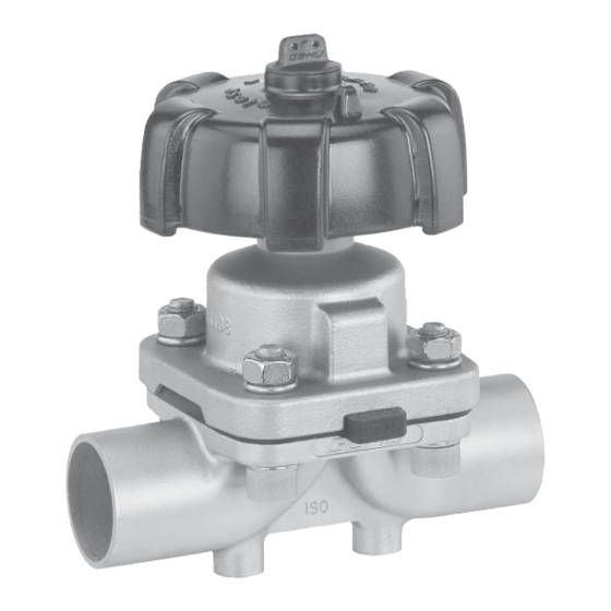
- Page 1 Membranventil Metall, DN 15 - 50 Diaphragm Valve Metal, DN 15 - 50 ORIGINAL EINBAU- UND MONTAGEANLEITUNG INSTALLATION, OPERATING AND MAINTENANCE INSTRUCTIONS 673_us...
-
Page 2: Table Of Contents
Funktion des GEMÜ-Ventils: Hinweise für Service- Sachgerechter Transport und Lagerung. und Bedienpersonal Installation und Inbetriebnahme durch Warnhinweise eingewiesenes Fachpersonal. Verwendete Symbole Bedienung gemäß dieser Einbau- und Begriff sbestimmungen Montageanleitung. Vorgesehener Einsatzbereich Ordnungsgemäße Instandhaltung. Auslieferungszustand Korrekte Montage, Bedienung und Wartung Technische Daten... -
Page 3: Hinweise Für Service
Montageanleitung beschrieben sind ® Bei Nichtbeachtung drohen dürfen nicht ohne vorherige Abstimmung Sachschäden. mit dem Hersteller durchgeführt werden. GEFAHR Sicherheitsdatenblätter bzw. die für die verwendeten Medien geltenden Sicherheitsvorschriften unbedingt beachten! Bei Unklarheiten: Bei nächstgelegener GEMÜ- Verkaufsniederlassung nachfragen. 673_us 3 / 40... -
Page 4: Verwendete Symbole
Verwendete Symbole Vorgesehener Einsatzbereich Das GEMÜ-Membranventil 673 ist für Gefahr durch heiße Oberfl ächen! den Einsatz in Rohrleitungen konzipiert. Es steuert ein durchfl ießendes Medium durch Handbetätigung. Gefahr durch ätzende Stoff e! Das Ventil darf nur gemäß den technischen Daten eingesetzt werden Quetschgefahr! (siehe Kapitel 6 "Technische Daten"). -
Page 5: Technische Daten
29,5 32,8 46,5 48,4 48,4 48,4 51,7 50,6 55,2 Kv-Werte ermittelt gemäß Norm IEC 534, Eingangsdruck 6 bar, ∆p 1 bar, Ventilkörperwerkstoff Edelstahl und Weichelastomermembrane. MG = Membrangröße Bestelldaten Gehäuseform Code Anschlussart Code Eine Seite Gewindestutzen, andere Seite Behälterkörper Kegelstutzen und Überwurfmutter, DIN 11851... - Page 6 Ventilkörperwerkstoff Code Steuerfunktion Code EN-GJS-400-18-LT (GGG 40.3) PFA-Auskleidung Manuell betätigt EN-GJS-400-18-LT (GGG 40.3) PP-Auskleidung 1.4435 - BN2 (CF3M) - Feinguss Fe<0,5% Antriebsausführung Code 1.4435 (ASTM A 351 CF3M ≙ 316L), Feinguss Mit Schließbegrenzung Handrad schwarz 1.4408, Feinguss Mit Schließbegrenzung Handrad weiß 1.4435 (316L), Schmiedekörper 1.4435 (BN2), Schmiedekörper Fe<0,5% * autoklavierbar...
-
Page 7: Herstellerangaben
Herstellerangaben Funktionsbeschreibung GEMÜ 673 ist ein Metall-Membranventil mit Durchgangs-, T- oder Behälterboden-Ablass- Transport körper bzw. Ausführung in Mehrwegeausfüh- Membranventil nur auf geeignetem rung. Antriebsgehäuse und -mechanik sind Lademittel transportieren, nicht stürzen, komplett aus Edelstahl. Das Ventil verfügt vorsichtig handhaben. serienmäßig über eine Schließbegrenzung... -
Page 8: Montage Und Bedienung
2. Antrieb mit Membrane vor Einschweißen des Ventilkörpers demontieren (siehe Montagearbeiten nur durch geschultes Kapitel 12.1). Fachpersonal. 3. Schweißstutzen abkühlen lassen. Geeignete Schutzausrüstung gemäß 4. Ventilkörper und Antrieb mit Membrane den Regelungen des Anlagenbetreibers wieder zusammen bauen (siehe Kapitel berücksichtigen. 12.4). -
Page 9: Bedienung
Montage bei Clampanschluss: Nach der Montage: Bei Montage der Clampanschlüsse Alle Sicherheits- und Schutzeinrichtungen entsprechende Dichtung zwischen wieder anbringen bzw. in Funktion setzen. Ventilkörper und Rohranschluss einlegen und mit Klammer verbinden. Die Dichtung 11.2 Bedienung sowie die Klammer der Clampanschlüsse sind nicht im Lieferumfang enthalten. -
Page 10: Einstellung Der Schließbegrenzung
Einstellung der Schließbegrenzung nur bei komplett montiertem Ventil (mit Membrane und Ventilkörper) und in kaltem Zustand! Zum Schutz der Dichtmembrane verfügen die Ventile der Baureihe GEMÜ 673 serien- mäßig über eine mechanisch einstellbare Schließbegrenzung. 5. Gewindespindel entsprechend den Ein- Standardeinstellung:... -
Page 11: Montage / Demontage Von Ersatzteilen
Wichtig: Nach Demontage alle Teile von Ver- schmutzungen reinigen (Teile dabei nicht beschädigen). Teile auf Be- schädigung prüfen, ggf. auswech- seln (nur Originalteile von GEMÜ verwenden). 12.2 Demontage Membrane Wichtig: 10. Handrad H in richtiger Position auf den Vor Demontage der Membrane... -
Page 12: Montage Der Konkav-Membrane
4. Bei Schwergängigkeit Gewinde prüfen, komplettes Ventil und Membrane beschädigte Teile austauschen (nur überprüfen und erneut nach obiger Originalteile von GEMÜ verwenden). Anleitung montieren. 5. Beim Verspüren eines deutlichen Widerstands Membrane soweit Druckstück und Antriebsfl ansch von unten zurückschrauben, bis Membran-Lochbild gesehen: mit Antriebs-Lochbild übereinstimmt. -
Page 13: Montage Der Konvex-Membrane
12.3.3 Montage der 12.4 Montage Antrieb Konvex-Membrane auf Ventilkörper 1. Antrieb A in Geschlossen-Position 1. Antrieb A in Geschlossen-Position bringen. bringen. 2. Neues Membranschild von Hand 2. Antrieb A ca. 20% öff nen. umklappen; bei großen Nennweiten 3. Alle Teile von Produktresten und saubere, gepolsterte Unterlage Verschmutzungen reinigen. -
Page 14: Inbetriebnahme
Membranventil auf Dichtheit und Funktion GEMÜ keinerlei Haftung. prüfen (Membranventil schließen und Nehmen Sie im Zweifelsfall vor wieder öff nen). Inbetriebnahme Kontakt mit GEMÜ auf. Bei neuen Anlagen und nach Reparaturen Leitungssystem bei voll 1. Geeignete Schutzausrüstung gemäß geöff netem Membranventil spülen (zum den Regelungen des Anlagenbetreibers Entfernen schädlicher Fremdstoff... -
Page 15: Demontage
(ATEX Richtlinie): Membranventil demontieren (siehe Ein Beiblatt zur Richtlinie 94/9/EG Kapitel 12.1 "Demontage Ventil (Antrieb liegt dem Produkt bei, sofern es vom Körper lösen)"). gemäß ATEX bestellt wurde. Hinweis zur Mitarbeiter- 16 Entsorgung schulung: Zur Mitarbeiterschulung nehmen Alle Ventilteile entsprechend Sie bitte über die Adresse auf der... -
Page 16: Fehlersuche / Störungsbehebung
19 Fehlersuche / Störungsbehebung Fehler Möglicher Grund Fehlerbehebung Medium entweicht aus Absperrmembrane auf Beschädigungen Absperrmembrane defekt Leckagebohrung* prüfen, ggf. Membrane tauschen Antrieb defekt Antrieb austauschen Ventil öff net nicht bzw. nicht Absperrmembrane nicht korrekt Antrieb demontieren, Membranmontage vollständig montiert prüfen, ggf. austauschen Ventil mit Betriebsdruck laut Datenblatt Betriebsdruck zu hoch betreiben... -
Page 17: Schnittbild Und Ersatzteile
20 Schnittbild und Ersatzteile Leckagebohrung Pos. Benennung Bestellbezeichnung Ventilkörper K600... Membrane 600...M Schraube Scheibe 673...S30... Mutter Antrieb 9673... 673_us 17 / 40... -
Page 18: Eg-Konformitätserklärung
CE-Zeichen bezogen auf die Druckgeräterichtlinie 97/23/EG gekennzeichnet und es wird keine Konformität erklärt. Geschäftsleitung UNTERNEHMENSBEREICH VENTIL-, MESS- UND REGELSYSTEME GEMÜ Gebr. Müller Apparatebau GmbH & Co. KG · Fritz-Müller-Str. 6-8 · D-74653 Ingelfi ngen-Criesbach Telefon +49(0)7940/123-0 · Telefax +49(0)7940/123-192 · info@gemue.de · www.gemue.de 673_us 18 / 40... -
Page 19: Notizen
Notizen 673_us 19 / 40... - Page 20 - and by any 12.3.3 Mounting a convex diaphragm additional assembly personnel. 12.4 Bonnet mounting Important: on the valve body The GEMÜ valve is sold to Commissioning sophisticated users. Training Inspection and servicing regarding safety issues must be Disassembly undertaken by each user.
-
Page 21: Notes For Servicing And Operating Personnel
Notes for servicing and In case of uncertainty operating personnel Consult the nearest GEMÜ sales offi ce. The installation, operating and maintenance instructions contain fundamental safety Warning notes notes that must observed during Wherever possible, warning notes are commissioning, operation and serving. -
Page 22: Symbols Used
Use the diaphragm valve only in accordance with the operating conditions specifi ed in the contract documentation and in the installation, operating and maintenance instructions. Delivery condition The GEMÜ diaphragm valve is supplied as a separately packed component. 673_us 22 / 40... -
Page 23: Technical Data
Technical data Working medium Nominal Max. operating Valve weight* size pressure [bar] Corrosive, inert, gaseous and liquid media which have no negative impact on the physical and chemical properties of EPDM PTFE the body and diaphragm material. 1100 1200 Operating temperature 1300 Liquids max. - Page 24 Valve body material Control function Code Code EN-GJS-400-18-LT (SG iron 40.3) PFA lined Manually operated EN-GJS-400-18-LT (SG iron 40.3) PP lined 1.4435 - BN2 (CF3M), investment casting Fe<0,5% Bonnet version Code 1.4435 (ASTM A 351 CF3M ≙ 316L), investment casting 34 With seal adjuster, black handwheel 1.4408, investment casting With seal adjuster, white handwheel...
-
Page 25: Manufacturer's Information
Manufacturer’s information Function description GEMÜ 673 is a metal diaphragm valve with a 2/2-way, T or tank bottom valve body or in Transport multi-port design. Bonnet and internals are made all of stainless steel. An integral optical Only transport the diaphragm valve... -
Page 26: Assembling The Diaphragm Valve
11.1 Assembling the Installation location: diaphragm valve CAUTION Do not apply external force to the valve. WARNING Choose the installation location so that The equipment is subject to the valve cannot be used as a foothold. pressure! Lay the pipeline so that the valve body ®... -
Page 27: Operation
Assembly - Clamp connections: Observe appropriate regulations for connections! When assembling clamp connections, insert a gasket between the body clamp and the adjacent After the assembly: piping clamp and join them using the Reactivate all safety and protective appropriate clamp fi tting. The gasket and devices. -
Page 28: Setting The Seal Adjuster
Only set the seal adjuster when the valve is completely assembled (with diaphragm and valve body) and in a cold condition! The valves type GEMÜ 673 have a mechanical seal adjuster as standard to protect the sealing diaphragm. Standard setting: The valve is sealed when the handwheel is 5. -
Page 29: Assembly / Disassembly Of Spare Parts
After disassembly, clean all parts of contamination (do not damage parts). Check parts for potential damage, replace if necessary (only use genuine parts from GEMÜ). 12.2 Removing the diaphragm Important: Before removing the diaphragm, 10. Push handwheel H in its original position... - Page 30 4. If it is diffi cult to screw it in, check the valve and diaphragm and reassemble thread, replace damaged parts (only use again proceeding as described genuine parts from GEMÜ). above. 5. When clear resistance is felt turn back the diaphragm anticlockwise until its bolt Compressor and bonnet fl...
-
Page 31: Bonnet Mounting On The Valve Body
12.4 Bonnet mounting compressor. on the valve body Adapter Recess of compressor Compressor 1. Move bonnet A to the closed position. 2. Open bonnet A approx. 20 %. 3. Clean all parts of the remains of product and contamination. Do not scratch or damage parts during cleaning! Backing 4. -
Page 32: Commissioning
If the plant is new and after repairs rinse by improper handling or third-party the piping system with a fully opened actions. diaphragm valve (to remove any harmful In case of doubt, contact GEMÜ before foreign matter). commissioning. Cleaning: The plant operator is responsible for... -
Page 33: Disassembly
17 Returns Clean the diaphragm valve. Returns must be made with a completed declaration of return (included). If not completed, GEMÜ cannot process credits or repair work but will dispose of the goods at the operator's expense. Note for returns:... -
Page 34: Troubleshooting / Fault Clearance
Troubleshooting / Fault clearance Fault Possible cause Fault clearance Medium escapes from leak Check valve diaphragm for damage, Valve diaphragm faulty detection hole* replace diaphragm if necessary Bonnet faulty Replace bonnet Valve doesn't open or Remove bonnet, check diaphragm doesn't open fully Valve diaphragm incorrectly mounted mounting, replace if necessary Operate valve with operating pressure... -
Page 35: Sectional Drawing And Spare Parts
20 Sectional drawing and spare parts Leak detection hole Item. Name Order description Valve body K600... Diaphragm 600...M Bolt Washer 673...S30... Bonnet 9673... 673_us 35 / 40... -
Page 36: Ec Declaration Of Conformity
They are not identifi ed with a CE label as per Pressure Equipment Directive 97/23/EC and no conformity is declared. Management VALVES, MEASUREMENT AND CONTROL SYSTEMS GEMÜ Gebr. Müller Apparatebau GmbH & Co. KG · Fritz-Müller-Str. 6-8 · D-74653 Ingelfi ngen-Criesbach Tel. +49(0)7940/123-0 · Telefax +49(0)7940/123-224 · info@gemue.de · www.gemue.de 673_us 36 / 40... -
Page 37: Notes
Notes 673_us 37 / 40... - Page 38 Rücksendeerklärung (Kopiervorlage) Gesetzliche Bestimmungen, der Schutz der Umwelt und des Personals erfordern es, diese Erklärung vollständig ausgefüllt und unterschrieben den Versandpapieren beizulegen. Wenn diese Erklärung nicht vollständig ausgefüllt ist oder den Versandpapieren nicht beigelegt ist wird Ihre Rücksendung nicht bearbeitet! Wurde das Ventil / Gerät mit giftigen, ätzenden, brennbaren, aggressiven oder wassergefährdenden Medien betrieben, alle mediumsberührten Teile sorgfältig entleeren, dekontaminieren und spülen.
-
Page 39: Goods Return Declaration
Goods return declaration (copy specimen) Legal regulations for the protection of the environment and personnel require that you include the completed and signed goods return declaration with your dispatch documents. If this declaration is not completed or not included with the dispatch documents, your return will not be processed! If the valve / device was operated with poisonous, corrosive, flammable, aggressive or water- endangering media, all medium wetted parts must be emptied carefully, decontaminated and rinsed. - Page 40 VENTIL-, MESS- UND REGELSYSTEME VALVES, MEASUREMENT AND CONTROL SYSTEMS GEMÜ Gebr. Müller Apparatebau GmbH & Co. KG · Fritz-Müller-Str. 6-8 · D-74653 Ingelfi ngen-Criesbach Telefon +49(0)7940/123-0 · Telefax +49(0)7940/123-192 · info@gemue.de ·www.gemue.de...
Need help?
Do you have a question about the 673 and is the answer not in the manual?
Questions and answers