
Related Manuals for GEM 616


Summary of Contents for GEM 616
- Page 1 GEMÜ 616 Manuell betätigtes Membranventil Manually operated diaphragm valve Betriebsanleitung Operating instructions Weitere Informationen Webcode: GW-616...
- Page 2 Alle Rechte, wie Urheberrechte oder gewerbliche Schutzrechte, werden ausdrücklich vorbehalten. All rights including copyrights or industrial property rights are expressly reserved. Dokument zum künftigen Nachschlagen aufbewahren. Keep the document for future reference. © GEMÜ Gebr. Müller Apparatebau GmbH & Co. KG 20.04.2021 GEMÜ 616 2 / 56...
-
Page 3: Table Of Contents
2 Sicherheitshinweise ..........3 Produktbeschreibung ..........Aufbau ..............Beschreibung ............Funktion ............... Optische Stellungsanzeige ......... Typenschild ............4 GEMÜ CONEXO ............5 Bestimmungsgemäße Verwendung ......6 Bestelldaten .............. Bestellcodes ............Bestellbeispiel ............. 10 7 Technische Daten ............. 11 Medium ..............11 Temperatur ............ -
Page 4: Allgemeines
Warnhinweises verwendet werden: Reaktion(en) auf Tätigkeiten – Aufzählungen Symbol Bedeutung Explosionsgefahr 1.3 Begriffsbestimmungen Betriebsmedium Medium, das durch das GEMÜ Produkt fließt. Aggressive Chemikalien! Steuerfunktion Mögliche Betätigungsfunktionen des GEMÜ Produkts. 1.4 Warnhinweise Heiße Anlagenteile! Warnhinweise sind, soweit möglich, nach folgendem Schema gegliedert: SIGNALWORT Art und Quelle der Gefahr Mögliches... -
Page 5: Sicherheitshinweise
Conexo-Info) 10. Sicherheitshinweise beachten. 3.2 Beschreibung 11. Das Produkt gemäß diesem Dokument bedienen. Das 2/2-Wege-Membranventil GEMÜ 616 ist für den Einsatz in 12. Das Produkt entsprechend der Leistungsdaten betreiben. sterilen Anwendungsbereichen konzipiert. 13. Das Produkt ordnungsgemäß instand halten. Die im Ventilantrieb verbauten Druckfedern schließen das 14. -
Page 6: Funktion
3.5 Typenschild Das Produkt ist aus Metall und mit einem Antriebsgehäuse Das Typenschild befindet sich am Antrieb. Daten des Typen- aus Edelstahl ausgestattet. GEMÜ 616 besitzt ein Handrad schilds (Beispiel): aus Edelstahl. Eine optische Stellungsanzeige befindet sich Ausführung gemäß Bestelldaten an der Spindel (eingefräste Ringe). -
Page 7: Gemü Conexo
Das Produkt ist bestimmungsgemäß nicht für den Einsatz in Wartungshistorien direkt verfügbar. Mit dem CONEXO Portal explosionsgefährdeten Bereichen geeignet. als zentrales Element lassen sich sämtliche Daten sammeln, ● Das Produkt gemäß den technischen Daten einsetzen. verwalten und weiterverarbeiten. Weitere Informationen zu GEMÜ CONEXO finden Sie auf: www.gemu-group.com/conexo www.gemu-group.com... -
Page 8: Bestelldaten
Stutzen ANSI/ASME B36.19M Schedule 5s PTFE/EPDM zweiteilig Stutzen ANSI/ASME B36.19M Schedule 40s Gewindeanschluss 7 Steuerfunktion Code Gewindemuffe DIN ISO 228 Manuell betätigt Gewindestutzen DIN 11851 8 Antriebsausführung Code Kegelstutzen und Überwurfmutter DIN 11851 Antriebsgröße 0TA Antriebsgröße 1T3 GEMÜ 616 8 / 56 www.gemu-group.com... - Page 9 Ra ≤ 6,3 µm (250 µin.) für medienberührte Oberflä- 1500 Ra max. 0,51 µm (20 µin.) für medienberührte chen, Oberflächen, innen mechanisch poliert gemäß ASME BPE SF5, innen/außen elektropoliert Ra ≤ 0,8 µm (30 µin.) für medienberührte Oberflä- 1502 chen, Ra max. 0,64 µm (25 µin.) für medienberührte gemäß...
-
Page 10: Bestellbeispiel
5 Werkstoff Ventilkörper 1.4435 (F316L), Schmiedekörper 6 Membranwerkstoff PTFE/EPDM zweiteilig 7 Steuerfunktion Manuell betätigt 8 Antriebsausführung Antriebsgröße 1T3 9 Oberfläche 1508 Ra ≤ 0,6 µm (25 µin.) für medienberührte Oberflächen, innen/außen elektropoliert 10 CONEXO ohne GEMÜ 616 10 / 56 www.gemu-group.com... -
Page 11: Technische Daten
Für den Einsatz im Bereich Dampferzeugung und -verteilung eig- nen sich besonders die Sitzventile GEMÜ 555 und 505. Bei Schnittstellen zwischen Dampf und Prozessleitungen hat sich die folgende Ventilanordnung bewährt: Sitzventil zum Absperren von Dampfleitungen und Membran- ventil als Schnittstelle zu den Prozessleitungen. -
Page 12: Produktkonformitäten
Anschlussarten Code MG = Membrangröße, Kv-Werte in m³/h Kv-Werte ermittelt gemäß DIN EN 60534, Eingangsdruck 5 bar, Δp 1 bar, Ventilkörperwerkstoff Edelstahl und Weichelastomermembrane. Die Kv-Werte für andere Produktkonfigurationen (z. B. andere Membran- oder Kör- perwerkstoffe) können abweichen. Im Allgemeinen unterliegen alle Membranen den Einflüssen von Druck, Tem- peratur, des Prozesses und den Drehmomenten mit denen diese angezogen werden. -
Page 13: Abmessungen
8 Abmessungen 8 Abmessungen 8.1 Einbaumaße øB Antriebs- øB ausführung 4 - 15 106,0 60,0 10 - 20 111,0 60,0 Maße in mm, MG = Membrangröße * CT = A + H1 (siehe Körpermaße) www.gemu-group.com 13 / 56 GEMÜ 616... -
Page 14: Körpermaße
Code 60: Stutzen ISO 1127 / EN 10357 Serie C / DIN 11866 Reihe B 2) Werkstoff Ventilkörper Code 40: 1.4435 (F316L), Schmiedekörper Code 42: 1.4435 (BN2), Schmiedekörper, Δ Fe < 0,5 % Code C3: 1.4435, Feinguss Code F4: 1.4539, Schmiedekörper GEMÜ 616 14 / 56 www.gemu-group.com... - Page 15 Code 64: Stutzen ANSI/ASME B36.19M Schedule 5s Code 65: Stutzen ANSI/ASME B36.19M Schedule 40s 2) Werkstoff Ventilkörper Code 40: 1.4435 (F316L), Schmiedekörper Code 42: 1.4435 (BN2), Schmiedekörper, Δ Fe < 0,5 % Code C3: 1.4435, Feinguss Code F4: 1.4539, Schmiedekörper www.gemu-group.com 15 / 56 GEMÜ 616...
- Page 16 12,0 1/2" 30,0 15,0 68,0 G 1/2 15,0 Maße in mm MG = Membrangröße n = Anzahl der Schlüsselflächen 1) Anschlussart Code 1: Gewindemuffe DIN ISO 228 2) Werkstoff Ventilkörper Code 37: 1.4408, Feinguss GEMÜ 616 16 / 56 www.gemu-group.com...
- Page 17 Rd 34 x 1/8 Maße in mm MG = Membrangröße 1) Anschlussart Code 6K: Kegelstutzen und Überwurfmutter DIN 11851 2) Werkstoff Ventilkörper Code 40: 1.4435 (F316L), Schmiedekörper Code 42: 1.4435 (BN2), Schmiedekörper, Δ Fe < 0,5 % www.gemu-group.com 17 / 56 GEMÜ 616...
- Page 18 Code 8T: Clamp DIN 32676 Reihe C, Baulänge FTF EN 558 Reihe 7, Baulänge nur bei Gehäuseform D 2) Werkstoff Ventilkörper Code 40: 1.4435 (F316L), Schmiedekörper Code 42: 1.4435 (BN2), Schmiedekörper, Δ Fe < 0,5 % Code F4: 1.4539, Schmiedekörper GEMÜ 616 18 / 56 www.gemu-group.com...
-
Page 19: Herstellerangaben
Passendes, funktionsfähiges und sicheres Werkzeug ver- 4. Lösungsmittel, Chemikalien, Säuren, Kraftstoffe u. ä. nicht ● wenden. mit GEMÜ Produkten und deren Ersatzteilen in einem Raum lagern. 1. Eignung des Produkts für den jeweiligen Einsatzfall sicher- stellen. 5. Das Produkt in Offen-Position lagern. -
Page 20: Einbaulage Beliebig
Funktion setzen. gen bzw. in Funktion setzen. 10.7 Nach dem Einbau 1. Antrieb montieren (siehe beiliegende Anleitung des An- triebs). 2. Alle Sicherheits- und Schutzeinrichtungen wieder anbrin- gen bzw. in Funktion setzen. GEMÜ 616 20 / 56 www.gemu-group.com... -
Page 21: Inbetriebnahme
2. Bei neuen Anlagen und nach Reparaturen empfehlen wir das Leitungssystem bei vollständig geöffnetem Produkt zu spülen. ð Schädliche Fremdstoffe wurden entfernt. ð Das Produkt ist einsatzbereit. 3. Das Produkt in Betrieb nehmen. www.gemu-group.com 21 / 56 GEMÜ 616... -
Page 22: Fehlerbehebung
Ventilkörper undicht oder korrodiert Ventilkörper auf Beschädigungen prüfen, ggf. Ventilkörper tauschen Handrad lässt sich nicht drehen Handrad defekt Antrieb austauschen Gewindespindel sitzt fest Gewindespindel entsprechend den Ein- satzbedingungen nachfetten, besonders wenn das Ventil autoklaviert wird; ggf. Antrieb austauschen. GEMÜ 616 22 / 56 www.gemu-group.com... -
Page 23: Inspektion Und Wartung
4. Anlage bzw. Anlagenteil gegen Wiedereinschalten sichern. alle 3 Striche = Auf-Stellung 5. Anlage bzw. Anlagenteil drucklos schalten. oberer und mittlerer Strich = Mittel-Stellung 6. GEMÜ Produkte, die immer in derselben Position sind, vier- oberer Strich = Geschlossen-Stellung mal pro Jahr betätigen. 13.2 Antrieb demontieren 1. -
Page 24: Druckstück Montieren
13.5.1 Konkav-Membrane montieren 3. Alle Teile von Verschmutzungen reinigen (Teile dabei nicht beschädigen). 13.5.1.1 Membrangröße 8 (Membrane zum Einknüpfen) 4. Teile auf Beschädigung prüfen, ggf. auswechseln (nur Ori- ginalteile von GEMÜ verwenden). Druckstückaussparung 13.4 Druckstück montieren HINWEIS Druckstückmontage ▶ Die Druckstückmontage betrifft nur die Membrangröße 10. - Page 25 Membran-Lochbild mit An- triebs-Lochbild übereinstimmt. 10. Membranschild von Hand fest auf die Stützmembrane drücken, so dass er zurückklappt und an der Stützmem- brane anliegt. 11. Steg von Druckstück und Membrane parallel ausrichten. Membranschild Membranpin www.gemu-group.com 25 / 56 GEMÜ 616...
-
Page 26: Antrieb Montieren
Produkt keine Rücksendeerklärung bei, erfolgt keine Gut- schrift bzw. keine Erledigung der Reparatur, sondern eine kos- tenpflichtige Entsorgung. 1. Das Produkt reinigen. 2. Rücksendeerklärung bei GEMÜ anfordern. 3. Rücksendeerklärung vollständig ausfüllen. 4. Das Produkt mit ausgefüllter Rücksendeerklärung an GEMÜ schicken. -
Page 27: Konformitätserklärung Nach 2014/68/Eu (Druckgeräterichtlinie)
EN 1983, AD 2000 Hinweis für Produkte mit einer Nennweite ≤ DN 25: Die Produkte werden entwickelt und produziert nach GEMÜ eigenen Verfahrensanweisungen und Qualitätsstandards, welche die Forderungen der ISO 9001 und der ISO 14001 erfüllen. Die Produkte dürfen gemäß Artikel 4, Absatz 3 der Druckgeräterichtlinie 2014/68/EU keine CE-Kennzeichnung tragen. - Page 28 Construction ............30 Description ............30 Function ............... 31 Optical position indicator ........31 Product label ............31 4 GEMÜ CONEXO ............32 5 Correct use ............... 32 6 Order data ..............33 Order codes ............33 Order example ............. 35 7 Technical data ............
-
Page 29: General Information
– Lists 1.3 Definition of terms Hot plant components! Working medium The medium that flows through the GEMÜ product. Control function The possible actuation functions of the GEMÜ product. 1.4 Warning notes Wherever possible, warning notes are organised according to... -
Page 30: Safety Information
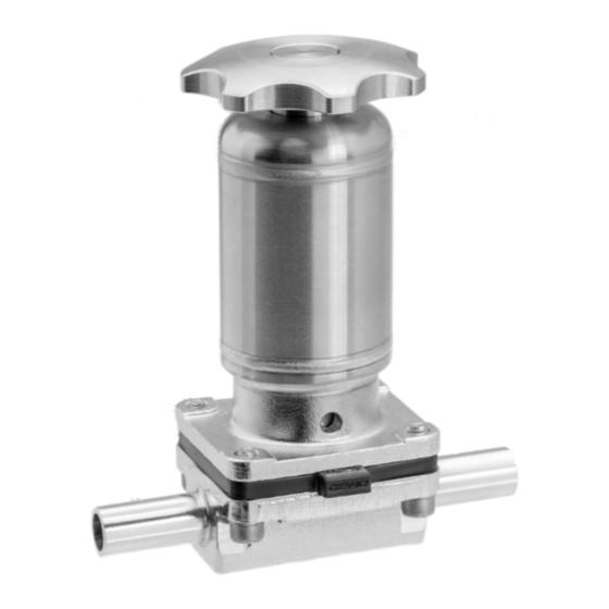
11. Operate the product in accordance with this document. 3.2 Description 12. Operate the product in accordance with the specifications. The GEMÜ 616 2/2-way diaphragm valve is designed for use 13. Maintain the product correctly. in sterile applications. 14. Do not carry out any maintenance work and repairs not de-... -
Page 31: Function
The product is made of metal and is equipped with a stainless The product label is located on the actuator. Product label steel actuator housing. GEMÜ 616 has a stainless steel hand- data (example): wheel. An optical position indicator is located on the spindle Design in accordance with order data (milled rings). -
Page 32: Gemü Conexo
The CONEXO portal acts as a central element, helping to ● Use the product in accordance with the technical data. collect, manage and process all data. For further information on GEMÜ CONEXO please visit: www.gemu-group.com/conexo GEMÜ 616 32 / 56... -
Page 33: Order Data
Clamp DIN 32676 series B, Ra ≤ 0.6 μm (25 μin.) for media wetted surfaces, 1507 face-to-face dimension FTF EN 558 series 7, mechanically polished internal length only for body configuration D www.gemu-group.com 33 / 56 GEMÜ 616... - Page 34 ASME BPE SF5, electropolished internal/external Ra max. 0.64 µm (25 µin.) for media wetted sur- faces, in accordance with ASME BPE SF6, electropolished internal/external 10 CONEXO Code Without Integrated RFID chip for electronic identification and traceability GEMÜ 616 34 / 56 www.gemu-group.com...
-
Page 35: Order Example
6 Diaphragm material PTFE/EPDM two-piece 7 Control function Manually operated 8 Actuator version Actuator size 1T3 9 Surface 1508 Ra ≤ 0.6 µm (25 µin.) for media wetted surfaces, electropolished internal/external 10 CONEXO Without www.gemu-group.com 35 / 56 GEMÜ 616... -
Page 36: Technical Data
PTFE diaphragms exposed to high temperature fluctuations. The maintenance cycles must be adapted accordingly. GEMÜ 555 and 505 globe valves are particularly suitable for use in the area of steam generation and distribution. The following valve arrangement for interfaces between steam pipes and process pipes has proven itself over time: A globe valve for shutting off steam pipes and a diaphragm valve as an interface to the process pipes. -
Page 37: Product Conformity
Threaded Threaded Clamp socket spigot, cone- spigot 0.09 0.09 0.09 0.09 0.15 0.09 0.21 0.18 0.09 0.18 0.30 0.33 0.30 0.17 0.30 0.26 0.35 0.43 0.30 0.43 MG = diaphragm size, weight in kg www.gemu-group.com 37 / 56 GEMÜ 616... -
Page 38: Dimensions
8 Dimensions 8.1 Installation dimensions øB Actuator øB version 4 - 15 106.0 60.0 10 - 20 111.0 60.0 Dimensions in mm, MG = diaphragm size * CT = A + H1 (see body dimensions) GEMÜ 616 38 / 56 www.gemu-group.com... -
Page 39: Body Dimensions
Code 60: Spigot ISO 1127/EN 10357 series C/DIN 11866 series B 2) Valve body material Code 40: 1.4435 (F316L), forged body Code 42: 1.4435 (BN2), forged body, Δ Fe < 0.5% Code C3: 1.4435, investment casting Code F4: 1.4539, forged body www.gemu-group.com 39 / 56 GEMÜ 616... - Page 40 Code 65: Spigot ANSI/ASME B36.19M schedule 40s 2) Valve body material Code 40: 1.4435 (F316L), forged body Code 42: 1.4435 (BN2), forged body, Δ Fe < 0.5% Code C3: 1.4435, investment casting Code F4: 1.4539, forged body GEMÜ 616 40 / 56 www.gemu-group.com...
- Page 41 G 1/2 27.0 15.0 Dimensions in mm MG = diaphragm size n = number of flats 1) Connection type Code 1: Threaded socket DIN ISO 228 2) Valve body material Code 37: 1.4408, investment casting www.gemu-group.com 41 / 56 GEMÜ 616...
- Page 42 MG = diaphragm size 1) Connection type Code 6K: Cone spigot and union nut DIN 11851 2) Valve body material Code 40: 1.4435 (F316L), forged body Code 42: 1.4435 (BN2), forged body, Δ Fe < 0.5% GEMÜ 616 42 / 56 www.gemu-group.com...
- Page 43 Code 8T: Clamp DIN 32676 series C, face-to-face dimension FTF EN 558 series 7, length only for body configuration D 2) Valve body material Code 40: 1.4435 (F316L), forged body Code 42: 1.4435 (BN2), forged body, Δ Fe < 0.5% Code F4: 1.4539, forged body www.gemu-group.com 43 / 56 GEMÜ 616...
-
Page 44: Manufacturer's Information
Use appropriate, functional and safe tools. 4. Do not store solvents, chemicals, acids, fuels or similar ● fluids in the same room as GEMÜ products and their spare 1. Ensure the suitability of the product for each respective parts. use. -
Page 45: Installation With Butt Weld Spigots
4. Connect the gasket between the body of the product and the pipe connection using clamps. 2. Re-attach or reactivate all safety and protective devices. 5. Re-attach or reactivate all safety and protective devices. 10.5 Installation with threaded spigots Fig. 3: Threaded spigots www.gemu-group.com 45 / 56 GEMÜ 616... -
Page 46: Commissioning
2. If the plant is new and after repairs, we recommend flush- ing the piping system with the product fully open. ð Harmful foreign matter has been removed. ð The product is ready for use. 3. Commission the product. GEMÜ 616 46 / 56 www.gemu-group.com... -
Page 47: Troubleshooting
Handwheel cannot be turned Handwheel faulty Replace the actuator Threaded spindle seized Dependent on the operating conditions, regrease the threaded spindle, especially a valve that is autoclaved; replace actu- ator if necessary. www.gemu-group.com 47 / 56 GEMÜ 616... -
Page 48: Inspection And Maintenance
* Optical position indicator: 5. Depressurize the plant or plant component. all 3 lines = open position 6. Actuate GEMÜ products which are always in the same po- upper and middle line = middle position sition four times a year. -
Page 49: Mounting The Compressor
3. Clean all parts of contamination (do not damage parts dur- ing cleaning). 13.5.1.1 Diaphragm size 8 (push-fit diaphragm) 4. Check parts for potential damage, replace if necessary (only use genuine parts from GEMÜ). Recess of compressor 13.4 Mounting the compressor NOTICE Compressor mounting ▶... - Page 50 10. Press the diaphragm face tightly onto the backing dia- phragm manually so that it returns to its original shape and fits closely on the backing diaphragm. 11. Align the weir of compressor and diaphragm in parallel. Diaphragm face Diaphragm pin GEMÜ 616 50 / 56 www.gemu-group.com...
-
Page 51: Mounting The Actuator
Returned goods can be processed only when this note is completed. If no return delivery note is included with the product, GEMÜ cannot process credits or repair work but will dispose of the goods at the operator's expense. -
Page 52: Declaration Of Conformity According To 2014/68/Eu (Pressure Equipment Directive)
EN 1983, AD 2000 Note for products with a nominal size ≤ DN 25: The products are developed and produced according to GEMÜ process instructions and quality standards which comply with the requirements of ISO 9001 and ISO 14001. According to Article 4, Paragraph 3 of the Pressure Equipment Directive 2014/68/EU these products must not be identified by a CE-label. - Page 53 GEMÜ 616 53 / 56 www.gemu-group.com...
- Page 54 GEMÜ 616 54 / 56 www.gemu-group.com...
- Page 55 55 / 56 GEMÜ 616...
- Page 56 Änderungen vorbehalten GEMÜ Gebr. Müller Apparatebau GmbH & Co. KG Subject to alteration *88756653* Fritz-Müller-Straße 6–8, 74653 Ingelfingen-Criesbach, Germany 04.2021 | 88756653 Phone +49 (0) 7940 1230 · info@gemue.de www.gemu-group.com...
Need help?
Do you have a question about the 616 and is the answer not in the manual?
Questions and answers