
Related Manuals for Amphenol APC Series


Summary of Contents for Amphenol APC Series
- Page 1 AI-18 APC series product installation (18-4) Revision Date Position Description Owner 2022/12/16 Initial release Andy Zhang...
-
Page 2: Table Of Contents
Contects Product composition ..........................3-4 Product assembly ............................5 Step 1: Stripping wire ..........................5 Step 2: Crimping contact ........................5 Step 3: Check after crimping ........................6 Step 4: Install contact ..........................6 Step 5: Install receptacle ......................... 7 Step 6: Mating plug and receptacle ...................... -
Page 3: Product Composition
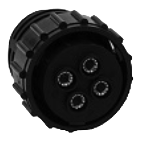
Product composition Note:Terminals need to be purchased separately and are not included in the connector part number. The number of terminals varies according to the insert arrangement : 18-4 (4 terminals), 18-11 (5 terminals), and 18-15 (16 terminals). Plug Description QTY. - Page 4 Rear mounting receptacle Description QTY. Description QTY. Sealing ring Gasket #10 contact Housing...
-
Page 5: Product Assembly
Product assembly Step 1: Stripping wire As shown in Figure 1 and Table 1, strip the wire, and ensure that the cut surface of the insulation layer is smooth, the wire is not damaged, and the cut surface of the wire is flush. Table 1 Contact size 6.0±0.4... -
Page 6: Step 3: Check After Crimping
Product assembly continue Step 3: Check after crimping Check appearance and pulling force after crimping terminals. The appearance must not be deformed. For details, see lPC620. The pulling force should be measured according to the tension value corresponding to the actual wire diameter, which should not be lower than the requirement of tension value in Table 2. -
Page 7: Step 5: Install Receptacle
Product assembly continue Step 5: Install receptacle As shown in Figure 4, install the receptacle on the panel. Please select the appropriate size of the panel (as shown in Figure 5). The screw holes in the rear panel are through holes, and the screw holes in the front panel are threaded holes. - Page 8 AI-18 Mini APC series product installation Revision Date Position Description Owner 2022/11/14 Initial release Andy Zhang Update figures and 2022/12/26 add checking force Andy Zhang after crimping...
- Page 9 Contects Product composition ..........................10 Product assembly ............................11 Step 1: Stripping wire ..........................11 Step 2: Crimping contact ........................11 Step 3: Check after crimping ........................11 Step 4: Install contact ..........................12 Step 5: Install receptacle ......................... 12 Step 6: Mating plug and receptacle ......................
-
Page 10: Product Composition
Product composition Note:Terminals need to be purchased separately and are not included in the connector part number. The number of terminals varies according to the insert arrangement : 18-4 (4 terminals), 18-11 (5 terminals), and 18-15 (16 terminals). Plug Description QTY. -
Page 11: Product Assembly
Product assembly Step 1: Stripping wire As shown in Figure 1, cut the wire. During cutting, ensure that the cut surface of the insulation layer is smooth, the wire is not damaged, and the cut surface of the wire is flush. Figure 1 Step 2: Crimping contact... -
Page 12: Step 4: Install Contact
Product assembly continues Step 4: Install contacts As shown in Figure 3, insert the crimped terminal and cable from the end of the connector according to the holes required by the customer. lf you hear a click, the terminal is installed in place. Gently pull the cable and ensure that the terminals are properly installed. -
Page 13: Step 6: Mating Plug And Receptacle
Product assembly continues Step 6: Mating plug and receptacle As shown in Figure 6, reset the plug first, align the arrow on the connecting nut with the mark on the plug housing, there will be an audible feedback when the reset is successful; Align the alignment marks on the plug and receptacle so that the terminals and connectors are not damaged when mating the plug and receptacle.
Need help?
Do you have a question about the APC Series and is the answer not in the manual?
Questions and answers