Table of Contents
Advertisement
Quick Links
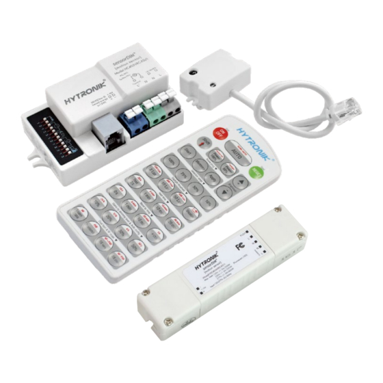
Tri-level Control HF Sensor
HC403VRC-KD/I HC404VRC-KD/I
Detached Version with Photocell Advance
Applications
Occupancy detector with tri-level dimming control suitable for indoor use.
Suitable for building into the xture:
Of ce / Commercial Lighting
Classroom
Use for new luminaire designs and installations
Features
Special photocell to measure and differentiate natural light from LED light from behind the xture cover
Tri-level dimming control based upon occupancy (also known as corridor function)
TM
1-10V dimming control method
One-key commissioning via programmable remote control
One-Key
Commissioning
One-touch daylight learning via remote control
Ambient daylight
threshold
Zero crossing detection circuit reduces in-rush current and prolongs relay life
Loop-In And Loop-Out Terminal for ef cient installation
Loop in
Loop out
5 Year, 50,000hr Warranty
Technical Data
Input Characteristics
Model No.
HC403VRC-KD/I HC404VRC-KD/I
Mains voltage
Stand-by power
Load ratings:
Capacitive
Warming-up
Safety and EMC
EMC standard (EMC)
Safety standard (LVD)
Radio Equipment (RED)
Certi cation
RED
TM
120~277VAC 50/60Hz
<0.5W
400VA @ 120VAC
800VA @ 230VAC
1000VA @ 277VAC
20s
EN55015, EN61000
EN60669-1
EN300440, EN301489,
EN62479
Semko, CB, CE , EMC, RED, RCM
IP20
Sensor Data
Model No.
HC403VRC-KD/I HC404VRC-KD/I
Sensor principle
Operation frequency
Transmission power
Detection angle
Sensitivity
Stand-by period
Environment
Operation temperature
Case temperature (Max.)
IP rating
High Frequency (microwave)
5.8GHz +/- 75MHz
<0.2mW
Max. ( O x H) 8m x 5m
O
O
30
~ 150
10% / 50% / 75% / 100%
5s ~ 30min (selectable)
2 ~ 50 lux, disabled
0s ~ 1h, +∞ (selectable)
10% / 20% / 30% / 50%
O
O
Ta: -20
C ~ +60
C
Tc: +80
O
C
IP20
Advertisement
Table of Contents

Related Manuals for Hytronik HC403VRC-KD/I


Summary of Contents for Hytronik HC403VRC-KD/I
- Page 1 Detection range 400VA @ 120VAC Max. ( O x H) 8m x 5m Detection angle 800VA @ 230VAC ~ 150 DIP Switch Settings (HC403VRC-KD/I): 1000VA @ 277VAC Sensitivity Warming-up 10% / 50% / 75% / 100% Hold-time 5s ~ 30min (selectable)
- Page 2 Sensor Main Body HC403VRC-KD/I (rectangular size) 63.2 28.8 Detection area Hold-time Daylight threshold Stand-by period Stand-by dimming level Sensor antenna interface 1-10V HC404VRC-KD/I (linear compact size) RJ12 (sensor antenna) Push 1-10V- L’ 1-10V+ 110.5 Detached Sensor Antenna Module Infrared remote receiver...
- Page 3 Function It’s well known that LED lights have a totally different spectrum to natural light. Hytronik uses this principle and comes up with special photocell and sophisticated software algorithm to measure and differentiate natural light from LED light from behind the xture cover, so that this photocell can ignore internal LED light and only respond to the natural light outside.
- Page 4 Manual Override (for HC404VRC-KD/I only) This sensor reserves the access of manual override function for end-user to switch on/off, or adjust the brightness by push-switch, which makes the product more user-friendly and offers more options to t some extra-ordinary demands: * Short Push (<1s): on/off function;...
- Page 5 Double L N terminal makes it easy for wire loop-in and loop-out, and saves the cost of terminal block and assembly time. Wiring Diagram 1-10V LED Driver L’ 1-10V HC403VRC-KD/I Note: this 1-10V output is isolated, SELV output. Do not connect the 1-10V terminals on driver X to Driver Y. LED Driver 1-10V+ 1-10V- HC404VRC-KD/I LED Driver L’...
- Page 6 2. Press button “SEMI-AUTO/AUTO” to initiate semi-auto mode. The xture is manually turned on by pressing the push-switch, and goes off automatically in this mode. (Absence detection mode) Reset Settings Press button “RESET”, all settings go back to DIP switch (HC403VRC-KD/I) or default settings (HC404VRC-KD/I). & A Shift Button Press button “Shift”, the LED on the top left corner will ash to indicate mode...
- Page 7 Press the button in zone “stand-by dimming level” to set the stand-by dimming level at 10% / 20% / 30% / 50%. Auto-con guration function All buttons in this zone are disabled. Dual tech & RF mode All buttons in this zone are disabled. DIP Switch Settings (HC403VRC-KD/I) Detection Range I – 100% 100% II – 75% Sensor sensitivity can be adjusted by selecting the combination on the DIP III –...
- Page 8 Stand-by period (corridor function) This is the time period you would like to keep at the low light output level I – 0s before it is completely switched off in the long absence of people. II – 10s III – 1min 1min Note: “0s”...
Need help?
Do you have a question about the HC403VRC-KD/I and is the answer not in the manual?
Questions and answers