Advertisement
Quick Links
Tri-level Control HF Sensor
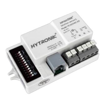
HC403VRC-KD
Detached Version with Daylight Monitoring
Applications
Occupancy detector with tri-level dimming control suitable for indoor use.
Suitable for building into the xture:
Of ce / Commercial Lighting
Classroom
Warehouse
Use for new luminaire designs and installations
Features
24 hour daylight monitoring dawn/dusk sensor
Daylight
Monitoring
Tri-level dimming control based upon occupancy (also known as corridor function)
TM
1-10V dimming control method
One-touch daylight learning via remote control
Ambient daylight
threshold
Zero crossing detection circuit reduces in-rush current and prolongs relay life
Loop-in and loop-out terminal for efficient installation
Loop in
Loop out
Technical Data
Input Characteristics
Model No.
HC403VRC-KD
Mains voltage
Stand-by power
Load ratings:
Capacitive
Warming-up
Safety and EMC
EMC standard (EMC)
Safety standard (LVD)
Radio Equipment (RED)
Certi cation
RED
120~277VAC 50/60Hz
<0.5W
400VA @ 120VAC
800VA @ 230VAC
1000VA @ 277VAC
20s
EN55015, EN61000
EN60669, AS/NZS60669
EN300440, EN301489,
EN62479
Semko, CB, CE , EMC, RED, RCM
IP20
Sensor Data
Model No.
Sensor principle
Operation frequency
Transmission power
Detection range:
SAM5
Detection angle
DIP Switch Settings (HC403VRC-KD):
Sensitivity
Hold-time
Daylight threshold
Stand-by period
Stand-by dimming level
Environment
Operation temperature
Case temperature (Max.)
IP rating
SAM5
High Frequency (microwave)
5.8GHz +/- 75MHz
<0.2mW
Max. ( O x H) 8m x 5m
30
O
~ 150
O
10% / 50% / 75% / 100%
5s ~ 30min (selectable)
2 ~ 50 lux, disabled
0s ~ 1h, +∞ (selectable)
10% / 20% / 30% / 50%
O
O
Ta: -20
C ~ +60
C
Tc: +80
O
C
IP20
Advertisement

Subscribe to Our Youtube Channel
Related Manuals for Hytronik HC403VRC-KD


Summary of Contents for Hytronik HC403VRC-KD
- Page 1 800VA @ 230VAC Max. ( O x H) 8m x 5m 1000VA @ 277VAC Warming-up Detection angle ~ 150 DIP Switch Settings (HC403VRC-KD): Sensitivity 10% / 50% / 75% / 100% Safety and EMC Hold-time 5s ~ 30min (selectable) EMC standard (EMC)
- Page 2 Sensor Main Body HC403VRC-KD (rectangular size) 63.2 28.8 Detection area Hold-time Daylight threshold Stand-by period Stand-by dimming level Sensor antenna interface 1-10V Sensor antenna module Infrared remote receiver Model SAM5 35.9 Cable side entry Super-compact sensor antenna, with optional cable entry (side Daylight Sensor entryand back entry).
-
Page 3: Typical Applications
Tri-level Control (Corridor Function) Hytronik builds this function inside the motion sensor to achieve tri-level control, for some areas which require a light change notice before switch-off. The sensor offers 3 levels of light: 100%-->dimmed light (natural light is insuf cient) -->off; and 2 periods of selectable waiting time: motion hold-time and stand-by period;... - Page 4 24h Daylight Monitoring Function Our innovative and patented software enables our antenna with built-in daylight sensor to provide a “smart photocell” function. This function is activated when stand-by period is set to “+∞ ”. Settings on this demonstration: Hold-time: 10min 21:00 21:10 21:40...
- Page 5 Double L N terminal makes it easy for wire loop-in and loop-out, and saves the cost of terminal block and assembly time. Wiring Diagram 1-10V LED Driver L’ 1-10V HC403VRC-KD Note: this 1-10V output is isolated, SELV output. Do not connect the 1-10V terminals on driver X to Driver Y.
- Page 6 Lux disable Disable Press this button, the built-in daylight sensor stops working, and all motion detected could turn on the lighting xture, no matter how bright the natural light is. Scene mode There are 4 scene modes fixed program built in the remote control to choose for different applications: Scene options Detection range Hold-time...
- Page 7 DIP Switch Settings (HC403VRC-KD) Detection Range I – 100% 100% II – 75% Sensor sensitivity can be adjusted by selecting the combination on the DIP III – 50% switches to t precisely for each speci c application. IV – 10% I –...
Need help?
Do you have a question about the HC403VRC-KD and is the answer not in the manual?
Questions and answers