Rockwell Automation Allen-Bradley FLEX 5000 Installation Instructions Manual
2-channel isolated-frequency input modules
Hide thumbs
Also See for Allen-Bradley FLEX 5000:
- User manual (170 pages) ,
- Installation instructions manual (16 pages) ,
- Installation instructions manual (12 pages)
Table of Contents
Advertisement
Quick Links
Installation Instructions
Original Instructions
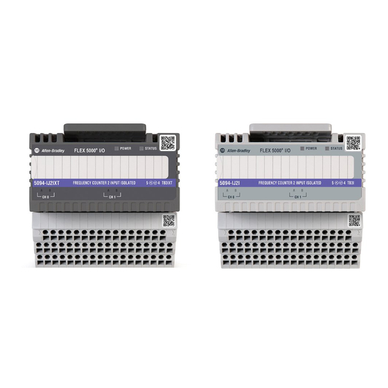
FLEX 5000 2-channel Isolated-frequency Input Modules
Catalog Numbers 5094-IJ2I, 5094-IJ2IXT
Topic
Product Overview
The 5094-IJ2I and 5094-IJ2IXT isolated-frequency input modules are essentially a tachometer with the capability of reporting frequency, acceleration, and direction.
FLEX 5000® I/O modules use the Producer/Consumer communication model. The Producer/Consumer communication model is an intelligent data exchange between modules and
other system devices in which each module produces data without first being polled.
FLEX 5000 I/O modules are used with some Logix 5000® controllers and configured with the Studio 5000 Logix Designer® application. For more information on which Logix 5000
controllers and Logix Designer application versions are compatible with FLEX 5000 I/O modules, see the publications that are listed in
Page
4
4
5
6
7
8
8
10
10
11
11
11
Additional Resources on page
11.
Advertisement
Table of Contents

Related Manuals for Rockwell Automation Allen-Bradley FLEX 5000


Summary of Contents for Rockwell Automation Allen-Bradley FLEX 5000
-
Page 1: Table Of Contents
Installation Instructions Original Instructions FLEX 5000 2-channel Isolated-frequency Input Modules Catalog Numbers 5094-IJ2I, 5094-IJ2IXT Topic Page About the Module Install a FLEX 5000 I/O System Required Components Install the Module Wire the Terminal Base Disconnect Wires from the Terminal Base Wiring Diagrams Power the System Remove the Module... - Page 2 WARNING: For Class I Division 2 applications, use only Class I Division 2 listed or recognized accessories and modules approved for use within the 5094 platform. When used in a Class I Division 2 hazardous location, this equipment must be mounted in a suitable enclosure with proper wiring method that complies with the governing electrical codes. Rockwell Automation Publication 5094-IN029A-EN-P - February 2023...
- Page 3 • This equipment shall be used within its specified ratings that are defined by Rockwell Automation. • Provision shall be made to help prevent the rated voltage from being exceeded by transient disturbances of more than 140% of the peak rated voltage when applied in Zone 2 environments.
-
Page 4: About The Module
Any illustrations, charts, sample programs, and layout examples that are shown in this publication are intended solely for the purposes of example. Since there are many variables and requirements that are associated with any particular installation, Rockwell Automation does not assume responsibility or liability for actual use based on the examples that are shown in this publication. -
Page 5: Required Components
The use of other DIN rail materials (for example, aluminum or plastic) that can corrode, oxidize, or are poor conductors can result in improper or intermittent grounding. Secure DIN rail to mounting surface approximately every 200 mm (7.8 in.) and use end-anchors appropriately. Be sure to ground the DIN rail properly. See the Industrial Automation Wiring and Grounding Guidelines, Rockwell Automation publication 1770-4.1 for more information. -
Page 6: Install The Module
If you do not install the end cap before powering the system, equipment damage or injury from electric shock can result. Once you have installed all your modules, install the end cap on the last connected terminal base. Rockwell Automation Publication 5094-IN029A-EN-P - February 2023... -
Page 7: Wire The Terminal Base
Connect cable shield ground to the shield bar accessory. Connect +V DC power to terminal SA+ on the left side of the terminal base. Connect V DC common to terminal SA– on the left side of the terminal base. Rockwell Automation Publication 5094-IN029A-EN-P - February 2023... -
Page 8: Disconnect Wires From The Terminal Base
Figure 1 - 5094-IJ2I and 5094-IJ2IXT Wiring Diagram: Magnetic Pickup Sensor IEC Type 3 Magnetic IEC Type 3 Magnetic COM0 COM0 COM1 COM1 – – Magnetic input – device Vortex Vortex Magnetic pickup Shield bar Rockwell Automation Publication 5094-IN029A-EN-P - February 2023... - Page 9 IEC Type 3 Magnetic IEC Type 3 Magnetic COM0 COM0 COM1 COM1 – – 24V DC 2-wire power DC input – supply Vortex Vortex 2-wire 24V DC IEC Type 3 input Shield bar Rockwell Automation Publication 5094-IN029A-EN-P - February 2023...
-
Page 10: Power The System
Worn contacts may create electrical resistance that can affect module operation Press and hold the release lever on the top of the module. Be sure to press the entire lever evenly. Pull the module off the terminal base. Rockwell Automation Publication 5094-IN029A-EN-P - February 2023... -
Page 11: Replace The Module
Provides specifications for the shield bar and jumper accessories. Industrial Automation Wiring and Grounding Guidelines, publication 1770-4.1 Provides general guidelines for installing a Rockwell Automation industrial system. Product Certifications website, rok.auto/certifications Provides declarations of conformity, certificates, and other certification details. - Page 12 Rockwell Otomasyon Ticaret A.Ş. Kar Plaza İş Merkezi E Blok Kat:6 34752 İçerenköy, İstanbul, Tel: +90 (216) 5698400 EEE Yönetmeliğine Uygundur Allen-Bradley, expanding human possibility, FactoryTalk, FLEX 5000, Logix 5000, Rockwell Automation, Studio 5000 Logix Designer, and TechConnect are trademarks of Rockwell Automation, Inc.
Need help?
Do you have a question about the Allen-Bradley FLEX 5000 and is the answer not in the manual?
Questions and answers