Rockwell Automation Allen-Bradley FLEX 5000 Installation Instructions Manual
High-speed counter i/o modules
Hide thumbs
Also See for Allen-Bradley FLEX 5000:
- User manual (170 pages) ,
- Installation instructions manual (16 pages) ,
- Installation instructions manual (12 pages)
Table of Contents
Advertisement
Quick Links
Installation Instructions
Original Instructions
FLEX 5000 High-speed Counter I/O Modules
Catalog Numbers 5094-HSC, 5094-HSCXT
Topic
Summary of Changes
This publication contains the following new or updated information. This list includes substantive updates only and is not intended to reflect all changes.
Topic
Updated template
Updated UK and European Hazardous Location Approval
Updated IEC Hazardous Location Approval
Updated Special Conditions for Safe Use
Updated Terminal base components
Updated Ground Considerations
Updated Module Specifications
Product Overview
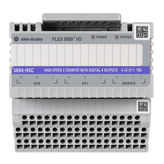
The 5094-HSC and 5094-HSCXT high-speed counter modules count incoming pulses from pulse generators, counters, limit switches, and other devices. The modules return counts
to a controller or activates outputs to execute a specific action. Six differential inputs comprise the counters.
FLEX 5000® I/O modules use the Producer-Consumer communication model. The Producer-Consumer communication model is an intelligent data exchange between modules and
other system devices in which each module produces data without first being polled.
I/O systems are used with some Logix 5000® controllers and configured with the Studio 5000 Logix Designer® application. For more information on which Logix 5000 controllers
and Logix Designer application versions are compatible with FLEX 5000 I/O modules, see the publications listed in
Page
1
1
4
5
6
7
7
8
9
12
12
13
13
13
Page
throughout
3
3
4
5
6
13
Additional Resources on page
13.
Advertisement
Table of Contents

Related Manuals for Rockwell Automation Allen-Bradley FLEX 5000


Summary of Contents for Rockwell Automation Allen-Bradley FLEX 5000
-
Page 1: Table Of Contents
Installation Instructions Original Instructions FLEX 5000 High-speed Counter I/O Modules Catalog Numbers 5094-HSC, 5094-HSCXT Topic Page Summary of Changes Product Overview About the Module Before You Begin Install the Module Install the End Cap Wire the Terminal Base Disconnect Wires from the Terminal Base Wiring Diagrams Power the System Remove the Module... - Page 2 Indien de apparatuur wordt gebruikt op een wijze die niet is gespecificeerd door de fabrikant, dan bestaat het gevaar dat de beveiliging van de apparatuur niet goed werkt. Rockwell Automation Publication 5094-IN009C-EN-P - May 2022...
- Page 3 • Comply to Standards IEC 60079-0, Explosive atmospheres - Part 0: Equipment - General requirements, Edition 7, Revision Date 2017, IEC 60079-7, 5.1 Edition revision date 2017, Explosive atmospheres - Part 7: Equipment protection by increased safety "e", reference IECEx certificate number IECEx UL 17.0075X. Rockwell Automation Publication 5094-IN009C-EN-P - May 2022...
-
Page 4: About The Module
Any illustrations, charts, sample programs, and layout examples shown in this publication are intended solely for the purposes of example. Since there are many variables and requirements associated with any particular installation, Rockwell Automation does not assume responsibility or liability for actual use based upon the examples shown in this publication. -
Page 5: Before You Begin
87.0 mm (3.43 in.) FLEX 5000 ® POWER STATUS 54.0 mm 54.0 mm (2.13 in.) (2.13 in.) 5094-HSC HIGH SPEED 2 COUNTER WITH DIGITAL 4 OUTPUTS 1 TB3 CH 0 CH 1 OUTPUTS Rockwell Automation Publication 5094-IN009C-EN-P - May 2022... -
Page 6: Install The Module
The use of other DIN rail materials (for example, aluminum or plastic) that can corrode, oxidize, or are poor conductors, can result in improper or intermittent grounding. Secure DIN rail to mounting surface approximately every 200 mm (7.8 in.) and use end-anchors appropriately. Be sure to ground the DIN rail properly. See the Industrial Automation Wiring and Grounding Guidelines, Rockwell Automation publication 1770-4.1 for more information. -
Page 7: Install The End Cap
(14 AWG) = Strip 15 mm ± 1 mm (0.59 in. ± 0.04 in.) of insulation from the wires Other = Strip 10 mm ± 1 mm (0.39 in. ± 0.04 in.) of insulation from the wires Rockwell Automation Publication 5094-IN009C-EN-P - May 2022... -
Page 8: Disconnect Wires From The Terminal Base
1. Turn the screwdriver counter-clockwise to open the terminal. Screw 2. Remove the wire. 1. Insert and hold a screwdriver in the slot above the terminal. Spring 2. Remove the wire. 3. Pull out the screwdriver. Screw-type TB Spring-type TB Rockwell Automation Publication 5094-IN009C-EN-P - May 2022... -
Page 9: Wiring Diagrams
Input Z0- Input A1+ Input A1- Input B1+ Input B1- Input Z1+ Input Z1- Output O0 Output O1 Output O2 Output O3 V DC Common 16 and 33 +V DC 34 and 51 Rockwell Automation Publication 5094-IN009C-EN-P - May 2022... - Page 10 Pull-up Resistor Value (R), Max 500 Ω 2250 Ω 5250 Ω Resistance values can change, depending on your application. The minimum resistor (R) value depends on the current sinking capability of the encoder. Rockwell Automation Publication 5094-IN009C-EN-P - May 2022...
- Page 11 Pull-up Resistor Value (R), Max 500 Ω 2250 Ω 5250 Ω Resistance values can change, depending on your application. The minimum resistor (R) value depends on the current sinking capability of the encoder. Rockwell Automation Publication 5094-IN009C-EN-P - May 2022...
-
Page 12: Power The System
Worn contacts may create electrical resistance that can affect module operation Press and hold the release lever on the top of the module. Be sure to press the entire lever evenly. Pull the module off the terminal base. Rockwell Automation Publication 5094-IN009C-EN-P - May 2022... -
Page 13: Replace The Module
Product Certifications website, rok.auto/certifications. Provides declarations of conformity, certificates, and other certification details. You can view or download publications at rok.auto/literature. To order paper copies of technical documentation, contact your local Allen-Bradley distributor or Rockwell Automation sales representative. Rockwell Automation Publication 5094-IN009C-EN-P - May 2022... - Page 14 FLEX 5000 High-speed Counter I/O Modules Installation Instructions Notes: Rockwell Automation Publication 5094-IN009C-EN-P - May 2022...
- Page 15 FLEX 5000 High-speed Counter I/O Modules Installation Instructions Notes: Rockwell Automation Publication 5094-IN009C-EN-P - May 2022...
- Page 16 Rockwell Otomasyon Ticaret A.Ş. Kar Plaza İş Merkezi E Blok Kat:6 34752 İçerenköy, İstanbul, Tel: +90 (216) 5698400 EEE Yönetmeliğine Uygundur Connect with us. Allen-Bradley, expanding human possibility, FactoryTalk, FLEX 5000, Logix 5000, Rockwell Automation, Studio 5000 Logix Designer, and TechConnect are trademarks of Rockwell Automation, Inc. EtherNet/IP is a trademark of ODVA, Inc.
Need help?
Do you have a question about the Allen-Bradley FLEX 5000 and is the answer not in the manual?
Questions and answers