Rockwell Automation Allen-Bradley FLEX 5000 Series Installation Instructions Manual
Hide thumbs
Also See for Allen-Bradley FLEX 5000 Series:
- User manual (170 pages) ,
- Installation instructions manual (16 pages) ,
- Installation instructions manual (12 pages)
Table of Contents
Advertisement
Quick Links
Installation Instructions
Original Instructions
FLEX 5000 Serial Modules
Catalog Numbers
5094-SERIAL, 5094-SERIALXT
Topic
Summary of Changes
This publication contains the following new or updated information. This list includes substantive updates only and is not intended to reflect all changes.
Topic
Updated template
Updated trademarks
Updated UK and European Hazardous Location Approval
Updated IEC Hazardous Location Approval
Updated Special Conditions for Safe Use
Updated Module Specifications
Product Overview
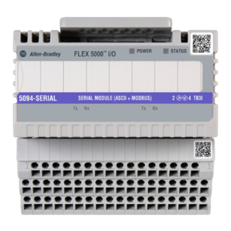
The 5094-SERIAL and 5094-SERIALXT serial modules provide a network interface to RS-232, RS-422, and RS-485 devices..
FLEX 5000® I/O modules use the Producer-Consumer communication model. The Producer-Consumer communication model is an intelligent data exchange between modules and
other system devices in which each module produces data without first being polled.
FLEX 5000 I/O modules are used with some Logix 5000® controllers and configured with the Studio 5000 Logix Designer® application. For more information on how which Logix
5000 controllers and Logix Designer application versions are compatible with FLEX 5000 I/O modules, see the publications listed in
Page
1
4
4
4
6
6
7
7
8
10
10
10
11
11
Page
throughout
1
3
3
3
11
Additional Resources on page
11.
Advertisement
Table of Contents

Related Manuals for Rockwell Automation Allen-Bradley FLEX 5000 Series


Summary of Contents for Rockwell Automation Allen-Bradley FLEX 5000 Series
-
Page 1: Table Of Contents
Installation Instructions Original Instructions FLEX 5000 Serial Modules Catalog Numbers 5094-SERIAL, 5094-SERIALXT Topic Page Summary of Changes About the Module Before You Begin Required Components Install the Module Install the End Cap Wire the Terminal Base Disconnect Wires from the Terminal Base Wiring Diagram Power the System Remove the Module... - Page 2 WARNING: For Class I Division 2 applications, use only Class I Division 2 listed or recognized accessories and modules approved for use within the 5094 platform. WARNING: When used in a Class I, Division 2, hazardous location, this equipment must be mounted in a suitable enclosure with proper wiring method that complies with the governing electrical codes. Rockwell Automation Publication 5094-IN028B-EN-P - August 2022...
- Page 3 The enclosure must be accessible only by the use of a tool. • This equipment shall be used within its specified ratings defined by Rockwell Automation. • Transient protection shall be provided that is set at a level not exceeding 140% of the peak rated voltage value at the supply terminals to the equipment.
-
Page 4: About The Module
Any illustrations, charts, sample programs, and layout examples shown in this publication are intended solely for the purposes of example. Since there are many variables and requirements associated with any particular installation, Rockwell Automation does not assume responsibility or liability for actual use based upon the examples shown in this publication. - Page 5 The use of other DIN rail materials (for example, aluminum or plastic) that can corrode, oxidize, or are poor conductors, can result in improper or intermittent grounding. Secure DIN rail to mounting surface approximately every 200 mm (7.8 in.) and use end-anchors appropriately. Be sure to ground the DIN rail properly. Refer to Industrial Automation Wiring and Grounding Guidelines, Rockwell Automation publication 1770-4.1 for more information.
-
Page 6: Install The Module
If the end cap is locked, pull the tab until it clicks. Locked Unlocked Align the end cap with interlocking pieces on the last terminal base in the system. Push the end cap towards the DIN rail. Press the locking tab until it clicks. Rockwell Automation Publication 5094-IN028B-EN-P - August 2022... -
Page 7: Wire The Terminal Base
1. Turn the screwdriver counter-clockwise to open the terminal. Screw 2. Remove the wire. 1. Insert and hold a screwdriver in the right-side terminal. Spring 2. Remove the wire. 3. Pull out the screwdriver. Screw-type TB Spring-type TB Rockwell Automation Publication 5094-IN028B-EN-P - August 2022... -
Page 8: Wiring Diagram
5094-SERIAL 9-pin D-sub connector DTE device 5094-SERIAL DTE device Signal Port Signal Port CH0 CH1 Port CH0 CH1 Port Shield Chassis Connector Connector Shield Chassis Connector Connector ground shield shield ground shield shield Rockwell Automation Publication 5094-IN028B-EN-P - August 2022... - Page 9 TxD+ TxD+ TxD+ IMPORTANT Place the termination resistor between RxD+ and RxD- to implement this wiring. TxD– TxD– TxD– RxD– RxD– RxD– Shield Chassis Connector Connector ground shield shield NC = No connection Rockwell Automation Publication 5094-IN028B-EN-P - August 2022...
-
Page 10: Power The System
Press and hold the release lever on the top of the module. Be sure to press the entire lever evenly. Pull the module off the terminal base. Replace the Module To replace the module, follow the steps that are described beginning at Install the Module on page Rockwell Automation Publication 5094-IN028B-EN-P - August 2022... -
Page 11: Module Specifications
IECEx temp code 5094-SERIAL – ISA S71.04 G2 Corrosion resistance classification 5094-SERIALXT – ISA S71.04 G3 Additional Resources These documents contain additional information concerning related products from Rockwell Automation. Resource Description FLEX 5000 Modules Specifications Technical Data, publication 5094-TD001 Provides specifications for FLEX 5000 EtherNet/IP adapters and FLEX 5000 modules. - Page 12 Rockwell Otomasyon Ticaret A.Ş. Kar Plaza İş Merkezi E Blok Kat:6 34752 İçerenköy, İstanbul, Tel: +90 (216) 5698400 EEE Yönetmeliğine Uygundur Connect with us. Allen-Bradley, expanding human possibility, FactoryTalk, FLEX 5000, Logix 5000, Rockwell Automation, Studio 5000 Logix Designer, and TechConnect are trademarks of Rockwell Automation, Inc EtherNet/IP is a trademark of ODVA, Inc Trademarks not belonging to Rockwell Automation are property of their respective companies.
Need help?
Do you have a question about the Allen-Bradley FLEX 5000 Series and is the answer not in the manual?
Questions and answers