Table of Contents
Advertisement
Quick Links
Installation Instructions
Original Instructions
FLEX 5000 Terminal Base Assembly Modules
Terminal Bases Assemblies: 5094-TB3, 5094-TB3S, 5094-TB3T, 5094-TB3TS, 5094-TB3W, 5094-TB3WS, 5094-TB3I, 5094-TB3IS, 5094-TB3IT,
5094-TB3ITS, 5094-TB32V, 5094-TB32VS, 5094-TB32C, 5094-TB32CS, 5094-TB3AC, 5094-TB3ACS, 5094-TB3XT, 5094-TB3SXT, 5094-TB3TXT,
5094-TB3TSXT, 5094-TB3WXT, 5094-TB3WSXT, 5094-TB3IXT, 5094-TB3ISXT, 5094-TB3ITXT, 5094-TB3ITSXT, 5094-TB32VXT, 5094-TB32VSXT,
5094-TB32CXT, 5094-TB32CSXT, 5094-TB3ACXT, 5094-TB3ACSXT
Mounting Bases: 5094-MB, 5094-MBXT
Catalog Numbers Removable Terminal Blocks: 5094-RTB3, 5094-RTB3S, 5094-RTB3T, 5094-RTB3TS, 5094-RTB3W, 5094-RTB3WS, 5094-RTB3I,
5094-RTB3IS, 5094-RTB3IT, 5094-RTB3ITS, 5094-RTB32V, 5094-RTB32VS, 5094-RTB32C, 5094-RTB32CS, 5094-RTB3AC, 5094-RTB3ACS, 5094-RTB3XT,
5094-RTB3SXT, 5094-RTB3TXT, 5094-RTB3TSXT, 5094-RTB3WXT, 5094-RTB3WSXT, 5094-RTB3IXT, 5094-RTB3ISXT, 5094-RTB3ITXT, 5094-RTB3ITSXT,
5094-RTB32VXT, 5094-RTB32VSXT, 5094-RTB32CXT, 5094-RTB32CSXT, 5094-RTB3ACXT, 5094-RTB3ACSXT
Topic
Summary of Changes
This publication contains the following new or updated information. This list includes substantive updates only and is not intended to reflect all changes.
18
Topic
Product Overview
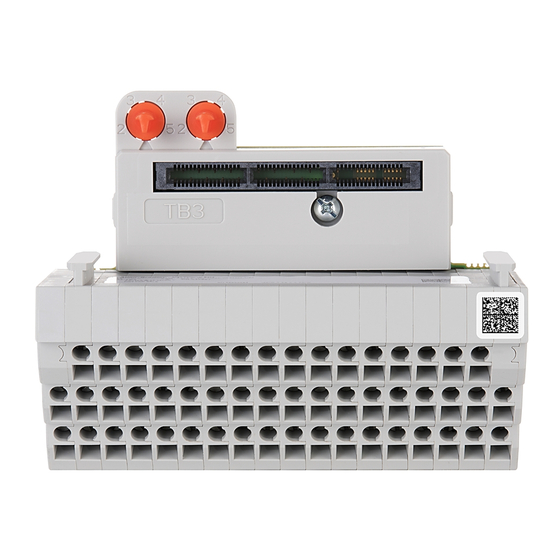
The FLEX 5000® terminal base assemblies comprise of either a 5094-MB or a 5094-MBXT, and one of the removable terminal blocks that are needed as a terminal base for your
specific FLEX 5000 I/O modules. Terminal base assemblies are a required part of the FLEX 5000 I/O family.
FLEX 5000 I/O family are used with some Logix 5000® controllers and configured with the Studio 5000 Logix Designer® application. For more information on which Logix 5000
controllers and Studio 5000 Logix Designer application versions are compatible with FLEX 5000 I/O modules, see the publications that are listed in
Page
1
1
5
8
10
10
11
12
13
14
14
17
17
19
Page
1
3, 4
5
17
17
Additional Resources on page
19.
Advertisement
Table of Contents

Related Manuals for Rockwell Automation Allen-Bradley5094-TB3


Summary of Contents for Rockwell Automation Allen-Bradley5094-TB3
-
Page 1: Table Of Contents
Installation Instructions Original Instructions FLEX 5000 Terminal Base Assembly Modules Terminal Bases Assemblies: 5094-TB3, 5094-TB3S, 5094-TB3T, 5094-TB3TS, 5094-TB3W, 5094-TB3WS, 5094-TB3I, 5094-TB3IS, 5094-TB3IT, 5094-TB3ITS, 5094-TB32V, 5094-TB32VS, 5094-TB32C, 5094-TB32CS, 5094-TB3AC, 5094-TB3ACS, 5094-TB3XT, 5094-TB3SXT, 5094-TB3TXT, 5094-TB3TSXT, 5094-TB3WXT, 5094-TB3WSXT, 5094-TB3IXT, 5094-TB3ISXT, 5094-TB3ITXT, 5094-TB3ITSXT, 5094-TB32VXT, 5094-TB32VSXT, 5094-TB32CXT, 5094-TB32CSXT, 5094-TB3ACXT, 5094-TB3ACSXT Mounting Bases: 5094-MB, 5094-MBXT Catalog Numbers Removable Terminal Blocks: 5094-RTB3, 5094-RTB3S, 5094-RTB3T, 5094-RTB3TS, 5094-RTB3W, 5094-RTB3WS, 5094-RTB3I,... - Page 2 Indien de apparatuur wordt gebruikt op een wijze die niet is gespecificeerd door de fabrikant, dan bestaat het gevaar dat de beveiliging van de apparatuur niet goed werkt. Rockwell Automation Publication 5094-IN010H-EN-P - May 2022...
-
Page 3: Added Ukex Certification Statements
• Comply to Standards IEC 60079-0, Explosive atmospheres – Part 0: Equipment – General requirements, Edition 7, Revision Date 2017, IEC 60079-7, 5.1 Edition revision date 2017, Explosive atmospheres - Part 7: Equipment protection by increased safety "e", reference IECEx certificate number IECEx UL 17.0075X. Rockwell Automation Publication 5094-IN010H-EN-P - May 2022... - Page 4 Any illustrations, charts, sample programs, and layout examples shown in this publication are intended solely for the purposes of example. Since there are many variables and requirements associated with any particular installation, Rockwell Automation does not assume responsibility or liability for actual use based upon the examples shown in this publication.
-
Page 5: About The Terminal Base Assemblies
Input/output terminal strips for connecting shields for all analog input, analog inputs/output wiring, commons, power output, and HSC module terminal base connections, and customer power supplies assemblies. Shield bar FRONT VIEW Rockwell Automation Publication 5094-IN010H-EN-P - May 2022... - Page 6 Input/output terminal strips for connecting analog input and analog output module inputs/output wiring, commons, power terminal base assemblies. connections, and customer power supplies Shield bar FRONT VIEW Rockwell Automation Publication 5094-IN010H-EN-P - May 2022...
- Page 7 I/O module guide rail NOTE: The 5094-STB shield bar accessory provides 16 screw terminals to extend Input/output terminal strips for connecting common/SA-. inputs/output wiring, commons, power connections, and customer power supplies Shield bar FRONT VIEW Rockwell Automation Publication 5094-IN010H-EN-P - May 2022...
-
Page 8: Before You Begin
• Screwdriver such as the 1492-N90 terminal block screwdriver with hardened 3 mm diameter blade Tools • Wire stripper • Wires For more information on available wire sizes and wire insulation-stripping length, see Terminal Base Assembly Specifications on page Rockwell Automation Publication 5094-IN010H-EN-P - May 2022... - Page 9 The use of other DIN rail materials (for example, aluminum or plastic) that can corrode, oxidize, or are poor conductors, can result in improper or intermittent grounding. Secure DIN rail to mounting surface approximately every 200 mm (7.8 in.) and use end-anchors appropriately. Be sure to ground the DIN rail properly. Refer to Industrial Automation Wiring and Grounding Guidelines, Rockwell Automation publication 1770-4.1 for more information.
-
Page 10: Assemble The Removable Terminal Block And The Mounting Base
To align the locking pegs with the holes on the mounting base, pivot the shield bar towards the back of the RTB. Press the shield bar up to the TB assembly until they snap together. Rockwell Automation Publication 5094-IN010H-EN-P - May 2022... -
Page 11: Mount The Terminal Base On A Din Rail
The RTB and TB modules do not support “Removal and Insertion Under Power” (RIUP) capability. Do not connect or disconnect the RTB or TB module while power is applied. Be sure power is removed before proceeding. Rockwell Automation Publication 5094-IN010H-EN-P - May 2022... -
Page 12: Install The End Cap
Once you have installed all your modules, install the end cap on the last connected terminal base. Make sure that the end cap is unlocked. If the end cap is locked, pull the tab until it clicks. Locked Unlocked Rockwell Automation Publication 5094-IN010H-EN-P - May 2022... -
Page 13: Wire The Terminal Base
If daisy chaining +V DC power to the next terminal base, connect a jumper from terminal SA+ on this base unit to terminal SA+ on the next base unit. Alternately, you can daisy chain SA+/+ and SA-/- on screw-type terminal bases using an SA power jumper accessory. Rockwell Automation Publication 5094-IN010H-EN-P - May 2022... -
Page 14: Disconnect Wires From The Terminal Base
5094-TB3 5094-TB3 5094-TB3 5094-TB3 5094-TB3 Module Power (MP) SA Power (SA) SA Power (SA) SA Power (SA) 18…32V DC, 10 A 18…32V DC, 10 A 18…32V DC, 10 A 18…32V DC, 10 A Rockwell Automation Publication 5094-IN010H-EN-P - May 2022... - Page 15 Wire optional shield bar: • To extend SA+ terminals, one per channel for 2-wire sensors, • To extend SA- terminals, one per channel for 2-wire actuators • To extend SA– terminals for 3-wire sensors Rockwell Automation Publication 5094-IN010H-EN-P - May 2022...
- Page 16 Wiring Connections for 5094-TB32V, 5094-TB32VS, 5094-TB32VXT, and 5094-TB32VSXT Terminal base with 5094-STB shield bar accessory NOTE: The 5094-STB shield bar accessory provides 16 screw terminals to extend voltage/SA+. Voltage Shield bar accessory Voltage Rockwell Automation Publication 5094-IN010H-EN-P - May 2022...
-
Page 17: Power The Modules
North American temp code UKEX/ATEX temp code IECEx temp code FLEX 5000 Mounting Base Specifications Attribute 5094-MB, 5094-MBXT Backplane Power (BP), max 100 mA @ 15V DC Backplane Power (Vcc), max 15 mA @ 3.3V Rockwell Automation Publication 5094-IN010H-EN-P - May 2022... - Page 18 50/60 Hz Input ratings (IN), max — 100 mA @ 10V DC — — 2 A @ 125V DC Output ratings (OUT), max — — 2 A @ 240V AC, — 50/60 Hz Rockwell Automation Publication 5094-IN010H-EN-P - May 2022...
-
Page 19: Additional Resources
Product Certifications website, rok.auto/certifications. Provides declarations of conformity, certificates, and other certification details. You can view or download publications at rok.auto/literature. To order paper copies of technical documentation, contact your local Allen-Bradley distributor or Rockwell Automation sales representative. Rockwell Automation Publication 5094-IN010H-EN-P - May 2022... - Page 20 Rockwell Otomasyon Ticaret A.Ş. Kar Plaza İş Merkezi E Blok Kat:6 34752 İçerenköy, İstanbul, Tel: +90 (216) 5698400 EEE Yönetmeliğine Uygundur Connect with us. Allen-Bradley, expanding human possibility, FactoryTalk, FLEX 5000, Logix 5000, Rockwell Automation, Studio 5000 Logix Designer, and TechConnect are trademarks of Rockwell Automation, Inc.
Need help?
Do you have a question about the Allen-Bradley5094-TB3 and is the answer not in the manual?
Questions and answers