Table of Contents
Advertisement
Quick Links
Assembly and operating instructions
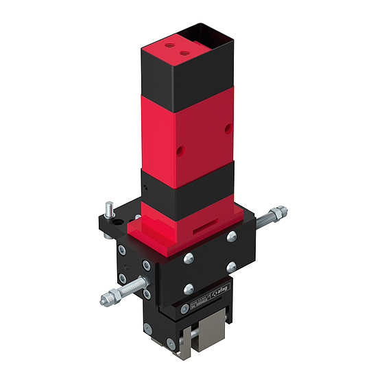
Gripper Module GMQ 32
GMQ 32/RM 16
Translation of the Original Assembly Instructions EN
GMQ 32/K
◼
GMQ 32/P
◼
GMQ 32/K RM16
◼
Assembly instructions EN
Rotary Gripper module
Order No.: 11010478
Order No.: 11010486
Order No.: 50094834
◼
GMQ 32 RM 16-25
◼
GMQ 32/RM 25
GMQ 32/P RM16
◼
GMQ 32/K RM 25
◼
GMQ 32/P RM 25
◼
◼
◼
19.04.2023
V3.0
Order No.: 50094825
Order No.: 50094853
Order No.: 50094845
1–62
Advertisement
Table of Contents

Subscribe to Our Youtube Channel
Related Manuals for Afag GMQ 32/RM 16


Summary of Contents for Afag GMQ 32/RM 16
- Page 1 Assembly and operating instructions Gripper Module GMQ 32 Rotary Gripper module ◼ GMQ 32/RM 16 GMQ 32/RM 25 Translation of the Original Assembly Instructions EN GMQ 32/K Order No.: 11010478 GMQ 32/P RM16 Order No.: 50094825 ◼ ◼...
- Page 2 Your Afag team © Subject to modifications The modules have been designed by Afag Automation AG according to the state of the art. Due to the constant technical development and improvement of our products, we reserve the right to make technical changes at any time.
-
Page 3: Table Of Contents
Table of contents Table of contents General ........................6 Contents and purpose of these assembly instructions ......... 6 Explanation of symbols................. 6 Additional symbols ..................7 Applicable documents .................. 8 Warranty ....................... 8 Liability ......................8 Safety instructions ....................9 General ...................... - Page 4 Design and description ..................27 Design of module GMQ 32 ................ 27 Product description GMQ 32 ..............28 Design GMQ 32/RM 16 - GMQ 32/RM 25..........29 Product description ..................29 Accessories ....................30 5.5.1 Accessories GMQ 32 ................30 5.5.2 Accessories RM 16 ................
- Page 5 Table of contents 9.3.2 Compressed air specifications ............. 51 9.3.3 Further maintenance ................52 Spare and wear parts lists ................52 9.4.1 Spare parts GMQ 32 ................53 9.4.2 Wear parts for RM 16 ................55 9.4.3 Wear parts for RM 16/360° ..............56 9.4.4 Wear parts RM 25 / RMZ 25/1 .............
-
Page 6: General
General General 1.1 Contents and purpose of these assembly instructions These assembly instructions contain important information on assembly, commissioning, functioning and maintenance of the GMQ modules to ensure safe and efficient handling and operation. Consistent compliance with these assembly instructions will ensure: ▪... -
Page 7: Additional Symbols
General Further warning signs: Where applicable, the following standardised symbols are used in this manual to point out the various potential health risks. Warning - Dangerous electrical voltage. Warning - Risk of injury from contact with hot surfaces. Warning - Risk of hand and finger injury due to uncontrolled movements of components. -
Page 8: Applicable Documents
▪ Wear parts (e.g., shock absorbers) are excluded from the warranty.* The warranty covers the replacement or repair of defective Afag parts. Further claims are excluded. * However, a customer has a right to a defect-free product. This does also apply to defective accessories and wear parts. -
Page 9: Safety Instructions
Safety instructions Safety instructions 2.1 General This chapter provides an overview of all important safety aspects to ensure safe and proper use of the gripper and optimal protection of personnel. Failure to follow the directions and safety instructions given in this instructions manual may result in serious hazards. -
Page 10: Obligations Of The Operator And The Personnel
▪ the operating company shall be solely responsible for such damage, and ▪ Afag does not accept any liability for damage caused by improper use. 2.4 Obligations of the operator and the personnel 2.4.1... -
Page 11: Personnel Requirements
Safety instructions 2.5 Personnel requirements 2.5.1 Personnel qualification The activities described in the assembly instructions require specific requisites at the level of professional qualifications of the personnel. Personnel not having the required qualification will not be able to asses the risks that may arise from the use of the module thus exposing himself and others to the risk of serious injury. -
Page 12: Changes & Modifications
2.7 Changes & Modifications No changes may be made to the GMQ module which have not been described in these assembly instructions or approved in writing by Afag Automation AG. Afag Automation AG accepts no liability for unauthorised changes or improper assembly, installation, commissioning, maintenance or repair work. - Page 13 Safety instructions Always keep the assembly instructions ready at hand at the workplace! Please, also observe: ▪ the general and local regulations on accident prevention and environmental protection, ▪ the safety information sheet for the module. WARNING Danger - Do not use in unsuitable environment ! The modules are designed for use in non-explosive atmospheres.
-
Page 14: Danger Due To Electricity
Safety instructions 2.8.2 Danger due to electricity WARNING Danger! Risk of electric shock! If work on electrical components is required, ensure that the work is carried out properly, failure to do so will cause serious or fatal injuries. ▪ Work on the machine's electrical equipment may only be performed by skilled electrician or trained personnel under the supervision of a skilled electrician in accordance with all relevant electrical regulations. -
Page 15: Technical Data
Technical data Technical data 3.1 Dimensional drawings 3.1.1 Gripper module GMQ 32 Fig. 1 Dimensional drawing - GMQ 32 ◼ ◼ ◼ Assembly instructions EN GMQ 32 RM 16-25 19.04.2023 V3.0 15–62... -
Page 16: Rotary Gripper Module Gmq 32 / Rm 16
Technical data 3.1.2 Rotary gripper module GMQ 32 / RM 16 Fig. 2 Dimensional drawing - GMQ 32/RM 16 16 – 62 ◼ ◼ ◼ Assembly instructions EN GMQ 32 RM 16-25 19.04.2023 V3.0... -
Page 17: Rotary Gripper Module Gmq 32 / Rm 25
Technical data 3.1.3 Rotary gripper module GMQ 32 / RM 25 Fig. 3 Dimensional drawing - GMQ 32 / RM 25 ◼ ◼ ◼ Assembly instructions EN GMQ 32 RM 16-25 19.04.2023 V3.0 17–62... -
Page 18: Technical Data
Technical data 3.2 Technical data 3.2.1 GMQ 32 Gripper Module Fig. 4 Technical data module GMQ 32 18 – 62 ◼ ◼ ◼ Assembly instructions EN GMQ 32 RM 16-25 19.04.2023 V3.0... -
Page 19: Rotary Gripper Module Gmq 32 / Rm 16
Technical data 3.2.2 Rotary gripper module GMQ 32 / RM 16 Fig. 5 Technical data module GMQ 32 / RM16 ◼ ◼ ◼ Assembly instructions EN GMQ 32 RM 16-25 19.04.2023 V3.0 19–62... -
Page 20: Rotary Gripper Module Gmq 32 / Rm 25
Technical data 3.2.3 Rotary gripper module GMQ 32 / RM 25 Fig. 6 Technical data module GMQ 32 / RM 25 20 – 62 ◼ ◼ ◼ Assembly instructions EN GMQ 32 RM 16-25 19.04.2023 V3.0... -
Page 21: Preferred Combinations Gmq 32
Technical data 3.3 Preferred combinations GMQ 32 Fig. 7 Preferred combinations GMQ 32 ◼ ◼ ◼ Assembly instructions EN GMQ 32 RM 16-25 19.04.2023 V3.0 21–62... -
Page 22: Module Loads Gmq 32
Technical data 3.4 Module loads GMQ 32 Fig. 8 Module loads - GMQ 32 22 – 62 ◼ ◼ ◼ Assembly instructions EN GMQ 32 RM 16-25 19.04.2023 V3.0... -
Page 23: Gripper Drive Gmq 32
Technical data 3.5 Gripper drive GMQ 32 Fig. 9 Gripper drive - GMQ 32 ◼ ◼ ◼ Assembly instructions EN GMQ 32 RM 16-25 19.04.2023 V3.0 23–62... -
Page 24: Transport, Packaging And Storage
Danger of injury when unpacking the rotary modules! The GMQ 32 modules are packed in the original packaging (cardboard box). The GMQ 32/RM 16 and GMQ 32 32/RM 25 modules are delivered assembled and are not specially packaged. If handled incorrectly, the module may fall out of the box when unpacked and cause limb injuries. -
Page 25: Transport
Transport, packaging and storage 4.3 Transport No liability can be assumed for damages caused by improper installation on the part of the operating company. The following conditions must be complied with for transport and storage: ▪ Storage temperature: 0-50 °C ▪... -
Page 26: Storage
Transport, packaging and storage 4.5 Storage If the module is stored for an extended period, observe the following: ▪ Do not store the modules outdoors or expose them to weather conditions. ▪ The storage space must be dry and dust free. ▪... -
Page 27: Design And Description
Design and description Design and description 5.1 Design of module GMQ 32 Fig. 11 GMQ 32 Internal or external clamping (exemplary) 1. Screws 6. Countersunk screws 2. Screws 7. Guide pin 3. Gripping jaws 8. Piston 4. Screws 9. Spring 5. -
Page 28: Product Description Gmq 32
Design and description 5.2 Product description GMQ 32 GMQ 32 Gripper Module The GMQ 32 gripping module is pneumatically operated and can be equipped with two different gripping jaws. The GMQ 32 is designed for gripping small parts. The piston diameter value is 32 mm. A built-in spring (Fig.4, 1) serves as a gripping force safety device in the depressurised state. -
Page 29: Design Gmq 32/Rm 16 - Gmq 32/Rm 25
Design and description 5.3 Design GMQ 32/RM 16 - GMQ 32/RM 25 Fig. 13 Rotary gripper module (exemplary) 1. Gripping jaws 5. Pneumatic connections RM 2. Rotary module 6. Pneumatic connections gripper drive 3. Gripper drive 7. Stop screw 4. Mounting bracket 8. -
Page 30: Accessories
Design and description 5.5 Accessories 5.5.1 Accessories GMQ 32 Designation Order no. Stop screw AS 08/15 11011202 Stop screw AS 08/25 11004991 Stop pin M8x1/25 11009229 Shock absorber SD 08/06 11004990 INI d6.5x44-Sn1.5-PNP-NO-M8x1 11005439 INI 8x8x38.5-Sn2.0-PNP-NO-M8x1 50338170 5.5.2 Accessories RM 16 Designation Order no. -
Page 31: Installation, Assembly And Setting
Installation, assembly and setting Installation, assembly and setting This chapter contains specific safety instructions and information regarding proper installation, assembly and setting of the modules including their connection to the control unit and the pneumatic system. 6.1 Safety instructions for installation and assembly CAUTION Danger of injury when connecting the modules to the control unit and the compressed-air system! -
Page 32: Installation & Assembly
Module centering To ensure high and repetitive accuracy of fit during assembling, operation and exchanging of a module, the components of the Afag modules are provided with a precise module centering unit. In the case of the gripping module, there are two centring pins Ø 4x6mm (Fig. - Page 33 Installation, assembly and setting Use the supplied centering bushings to position the modules. Insert the centering bushings in two diagonally opposite holes of the attachment grid. The dimensions of the mounting holes and the distances between holes are chap. 3 „Technical Data“. indicated in the dimensional drawings in ◼...
-
Page 34: Tightening Torques For Screws
Installation, assembly and setting 6.2.3 Tightening torques for screws For assembling use screws with the following minimum specifications: Standard VDI 2230 Screw strength Category 8.8 Surface: Galvanized blue, oiled or greased Thread Tightening torque 1.1 … 1.4 Nm 2.6 … 3.3 Nm 5.2 …... - Page 35 4. Maintenance unit 2. Throttle check valve P. Compressed air connection 3. Directional control valve (standard 5/2) Pneumatic connections module GMQ 32/RM 16, GMQ 32/RM 25 Fig. 16 Pneumatic circuit diagram rotary gripper module 1. Gripper drive 4. Maintenance unit 2.
-
Page 36: Mounting The Initiators
Installation, assembly and setting 6.2.5 Mounting the initiators Plug-in and screw-in proximity switches (6.5 mm or 8x8 mm) with proximity switch holder are used for end position detection of the modules. The initiators and holders are not included in the scope of delivery of the PMP module! WARNING Danger - Do not use in unsuitable environment ! The initiators are designed for use in non-explosive atmospheres. - Page 37 Installation, assembly and setting Mounting the initiator 6.5 mm - GMQ 32 Fig. 18 Mounting the proximity switches (6.5 mm) To install the 6.5 mm proximity switch, proceed as follows: 1. Screw the initiator holder (1) onto the stop screw. 2.
- Page 38 Installation, assembly and setting Mounting initiator 8x8 mm Fig. 19 Mounting the proximity switches (8x8 mm) To install the 8x8 mm initiator, proceed as follows: 1. Screw the initiator (5) onto the initiator holder (7) with screws (6). The switching point of the initiator must cover the hole of the initiator holder (see arrow).
-
Page 39: Assembly Of The Gripping Jaws
Installation, assembly and setting 6.2.6 Assembly of the gripping jaws Gripper drive Fig. 20 Mounting the gripping jaws For assembly the gripping jaws proceed as follows: 1. Insert the centring ring (5) into the piston rod (6). 2. Position the centring sleeve (1) on the centring ring (5). 3. -
Page 40: Settings
Installation, assembly and setting 6.3 Settings This chapter contains information on the adjustment work to be carried out on the modules. NOTICE No liability can be assumed for damages caused by accordance work carried out on the modules on the part of the operator. The gripping modules can be adjusted to the desired combination and the module can be optimally set at the factory! 6.3.1... -
Page 41: Adjusting The Stop Screw And Stop Pin
Installation, assembly and setting 6.3.2 Adjusting the stop screw and stop pin The GMQ can be equipped with a wide range of stop screws. These must be ordered separately. The stop screw can be combined with an initiator holder and initiator switch 6.5 mm or with an angle initiator holder for end position detection. -
Page 42: Stroke Adjustment Of The Gmq 32 Grippers
Installation, assembly and setting Adjustment of stop pin M8x1/25 on the module GMQ 32 For Setting the positioning pins proceed as follows: 1. Adjust the stroke by adjusting the stop pin (3). One turn = 1 mm 2. Secure stop pin with locknut (4). Stopping accuracy: +- 0.01 mm The process is complete. -
Page 43: Conversion Of The Gmq Module
If required, the modules can be converted to another function. Special tools must be used to convert the GMQ 32/RM 16 and GMQ 20/RM 25 modules. Therefore, these modules must be sent to Afag for conversion. -
Page 44: Conversion Of The Gmq 32 To Internal Clamping
Installation, assembly and setting 6.4.1 Conversion of the GMQ 32 to internal clamping To convert the GMQ 32 to internal clamping, proceed as follows: 1. Loosen screw (1+2). 2. Dismount the gripping jaw (3). 3. Loosen the screws (4+6). 4. Remove the guide pin (7). 5. -
Page 45: Conversion Of The Gmq 32 To Double-Acting
Installation, assembly and setting 6.4.2 Conversion of the GMQ 32 to double-acting To convert the GMQ 32 to internal clamping, proceed as follows: 1. Loosen screw (1+2). 2. Dismount the gripping jaw (3). 3. Loosen the countersunk screws (6). 4. Remove the guide pin (7). 5. -
Page 46: Commissioning
Commissioning Commissioning 7.1 Safety instructions for commissioning CAUTION Danger of injury by moving components! Limbs can be crushed by moving components! ▪ Work on and with the modules may only be carried out by qualified personnel. ▪ Make sure that there are no persons or tools in the working area of the modules. -
Page 47: Fault Elimination
Fault elimination Fault elimination 8.1 General Notes This chapter contains general information and safety instructions for troubleshooting. 8.2 Safety instructions for troubleshooting WARNING Danger of injury due to improper work! Poorly performed troubleshooting work can lead to serious injuries and damage to property. - Page 48 Fault elimination 8.3 Table Fault causes and remedy GMQ 32, GMQ 32/RM16, GMQ 32/RM25 Defective components must be replaced exclusively by Afag original spare parts. Fault Possible cause Remedy: ▪ No compressed air ▪ Check connections Gripper does not open/close ▪...
-
Page 49: Maintenance And Repair
Maintenance and repair Maintenance and repair 9.1 General notes The modules are almost maintenance-free. Nevertheless, some maintenance work must be carried out to ensure an optimum operating condition of the modules. This chapter describes the required maintenance activities. Each Module is accompanied by a safety information sheet. This information sheet must be read carefully by every person who carries out work on and with the module. -
Page 50: Maintenance Activities And Maintenance Intervals
Maintenance and repair 9.3 Maintenance activities and maintenance intervals The modules are almost maintenance-free. Nevertheless, some maintenance work must be carried out to ensure an optimum operating condition of the modules. 9.3.1 Overview of the maintenance points Fig. 25 Maintenance GMQ 32, GMQ 32/RM16, GMQ 32/RM25 System Interval Maintenance point... -
Page 51: Compressed Air Specifications
If the modules are used in an ionised air environment, there is a risk that exposed parts could corrode. ▪ Always grease exposed parts e.g., flanges, shafts, guides and jaws regularly. ▪ Afag standard lubrication: Staburax NBU8EP (flat guides), Blasolube 301 (piston rods) 9.3.2 Compressed air specifications The modules are lifetime lubricated and can be operated with lubricated or non- lubricated compressed air. -
Page 52: Further Maintenance
Afag for warranty repair within the warranty period. After expiry of the warranty period, the customer may replace or repair defective modules or wear parts himself or send them to the Afag repair service. Please note that Afag does not assume any warranty for modules that have... -
Page 53: Spare Parts Gmq 32
After the warranty period has expired, the customer can also carry out the repair himself and order the corresponding wearing parts sets. 9.4.1 Spare parts GMQ 32 Item Designation Dimensions Supplier number Order no. Housing Afag 11009094 Piston Afag 11009089 Piston rod Afag 11005777 Guide pin Afag 11009091... - Page 54 Maintenance and repair Fig. 26 Overview of spare and wear parts 54 – 62 ◼ ◼ ◼ Assembly instructions EN GMQ 32 RM 16-25 19.04.2023 V3.0...
-
Page 55: Wear Parts For Rm16
Wear parts for RM16 Item Designation Supplier number Order no. Wear parts Afag 11002514 Wear parts Afag 11007844 Fig. 27 Wear parts RM 16 ◼ ◼... -
Page 56: Wear Parts For Rm 16/360
Maintenance and repair 9.4.3 Wear parts for RM 16/360° Item Designation Supplier number Order no. Wear parts Afag 11002514 Wear parts Afag 11007844 Fig. 28 Wear parts RM 16/ 360° 56 – 62 ◼ ◼ ◼ Assembly instructions EN GMQ 32 RM 16-25 19.04.2023... -
Page 57: Wear Parts Rm 25 / Rmz 25/1
Maintenance and repair 9.4.4 Wear parts RM 25 / RMZ 25/1 Item Designation Supplier number Order no. Wear parts Afag 11002517 Wear parts Afag 11002519 Fig. 29 Wear parts RM 25 / RMZ 25/1 ◼ ◼ ◼ Assembly instructions EN GMQ 32 RM 16-25 19.04.2023... -
Page 58: Wear Parts Rmz 25/2
Maintenance and repair 9.4.5 Wear parts RMZ 25/2 Item Designation Supplier number Order no. Wear parts Afag 11002519 Fig. 30 Wear parts RM 25/2 58 – 62 ◼ ◼ ◼ Assembly instructions EN GMQ 32 RM 16-25 19.04.2023 V3.0... -
Page 59: Decommissioning, Disassembly, Disposal
Decommissioning, disassembly, disposal 10 Decommissioning, disassembly, disposal The gantry modules must be properly dismounted after use and disposed of in an environmentally friendly manner. 10.1 Safety instructions for decommissioning, disassembling and disposal WARNING Risk of injury due to improper decommissioning, disassembly and disposal! Improperly carried out activities can result in considerable material damage and serious injury. -
Page 60: Disposal
Decommissioning, disassembly, disposal 10.4 Disposal The module must be disposed of properly at the end of their service life and the raw materials used must be recycled. Observe the legal regulations and company requirements. The modules must not be disposed of as a complete unit. Dismantle the modules and separate the various components according to type of material and dispose of them properly: ▪... -
Page 61: Declaration Of Incorporation
Product description Gripping modules / rotary gripper modules (pneumatic) Type: GMQ 32 / GMQ 32/RM 16, GMQ 32/RM 25 Consecutive serial no. 50XXXXXX complies with the following essential health and safety requirements of the Machinery Directive 2006/42/EC at the time of declaration: 1.1;... - Page 62 Afag Automation Americas Afag Automation APAC Schaeff Machinery & Services LLC. Afag Automation Technology (Shanghai) Co., Ltd. 883 Seven Oaks Blvd, Suite 800 Room 102, 1/F, Bldg. 56, City Of Elite Smyrna, TN 37167 No.1000, Jinhai Road, Pudong New District...
Need help?
Do you have a question about the GMQ 32/RM 16 and is the answer not in the manual?
Questions and answers