Table of Contents
Advertisement
Advertisement
Chapters
Table of Contents

Related Manuals for Unitronics Vision 230


Summary of Contents for Unitronics Vision 230
- Page 1 User Guide Vision 230 Vision 260 Vision 280 01/04 V200-21-G20...
- Page 3 Unitronics products such as styles, templates, icons, screen displays, looks, etc. Duplication and/or any unauthorized use thereof are strictly prohibited without prior written permission from Unitronics.
- Page 5 Preface This guide contains essential information for Vision OPLC™ users. Note that illustrations showing the Vision230 (V230) also refer to the models Vision260 (V260) and Vision280 (V280), except where specified. Warnings and Safety Guidelines Read this section carefully before installing and operating the device. Chapter 1: Overview Contains a general description of the device’s features and functions.
-
Page 6: Table Of Contents
Vision 230/260/280 User Guide Table of Contents Preface Guidelines for user safety and equipment protection............iii Warnings ..........................iv Chapter 1: Overview ™ Introducing the Vision OPLC ....................5 Technical Description Safety Guidelines Chapter 2: Mounting Before You Begin ........................9 Safety and Environmental Guidelines .................10 Mounting..........................11... -
Page 7: Preface
Preface Warnings and Safety Guidelines Guidelines for user safety and equipment protection This manual is intended to aid trained and competent personnel in the installation of this equipment as defined by the European directives for machinery, low voltage, and EMC. Only a technician or engineer trained in the local and national electrical standards should perform tasks associated with the electrical wiring of this device. -
Page 8: Warnings
All examples and diagrams shown in the manual are intended to aid understanding. They do not guarantee operation. • Unitronics accepts no responsibility for actual use of this product based on these examples. • Due to the great variety of possible applications for this equipment, the user must assess the suitability of this product for specific applications. -
Page 9: Chapter 1: Overview
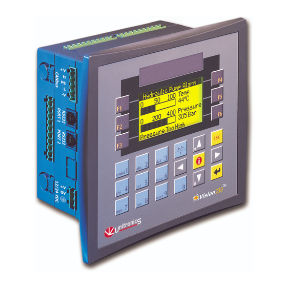
™1 Vision OPLCs are programmable logic controllers that comprise an integral operating panel. Compactly designed, these controllers are compatible with different types of Unitronics’ I/O modules. This allows you to build Vision-controlled systems capable of automating a broad range of analog and digital applications. All Vision OPLCs offer RS232 communications, CANbus networking options, and a real-time clock (RTC). -
Page 10: Technical Description
Vision 230/260/280 User Guide Two types of I/O modules are compatible with Vision OPLCs. I/O modules are available in a variety of models. Snap-in I/O Modules plug directly into the back of a Vision OPLC, creating a self-contained PLC unit with a local I/O configuration. I/O Expansion Modules can also be easily integrated to greatly extend the system’s control capacity. - Page 11 Chapter 1: Overview Communications RS232 The controller comprises 2 COM ports. These may be used to download programs from a PC, or to establish communications with devices using the RS232 protocol. CANbus The controller comprises 1 port for CANbus networking purposes. Additional communication port Optional communication channel;...
-
Page 12: Safety Guidelines
Vision 230/260/280 User Guide Data Type Symbol Data Type Symbol Memory Bits (coils): Timers: 2048 192, 32 bit Memory Integers (registers): Counters: 1600, 16 bit Memory Long Integers: Inputs: 256, 32 bit Double Word (unsigned): Outputs: 64, 32 bit Memory Floats: System data types, listed below, are linked to certain values or controller functions and are reserved for use by the system. -
Page 13: Chapter 2: Mounting
Chapter 2: Mounting This chapter gives detailed panel mounting instructions. Before You Begin Before you begin installation procedures, check the contents of the controller kit. Standard kits contain the controller, a 3-pin power supply connector, a 5-pin CANbus connector, and 4 mounting brackets, each with a screw inserted. -
Page 14: Safety And Environmental Guidelines
Vision 230/260/280 User Guide Safety and Environmental Guidelines • Do not install in areas with: excessive or conductive dust, corrosive or flammable gas, moisture or rain, excessive heat, regular impact shocks or excessive vibration. • Do not place in water or let water leak onto the controller. -
Page 15: Mounting
Chapter 2: Mounting Mounting Before you begin, note that the mounting panel cannot be more than 5 mm thick. To maximize system performance, avoid electromagnetic interference by mounting the controller on a metal panel and earthing the power supply according to the details in Figure 7, page 16. -
Page 16: Figure 3. V230 Panel Cut-Out-Front View
Vision 230/260/280 User Guide Figure 3. V230 Panel Cut-out—Front View... -
Page 17: Figure 4. V260/V280 Panel Cut-Out-Front View
Chapter 2: Mounting Figure 4. V260/V280 Panel Cut-out—Front View Figure 5. Earth Assembly... -
Page 18: Figure 6. Panel Mounted-Rear View
Vision 230/260/280 User Guide When properly mounted, the controller is squarely situated in the panel cut-out as shown below. Figure 6. Panel Mounted—Rear View... -
Page 19: Chapter 3: Power Supply
Chapter 3: Power Supply Power Supply The controller requires an external 12 or 24VDC power supply. The permissible input voltage range is 10.2-28.8VDC, with less than 10% ripple. You must use an external circuit protection device as shown in Figure 7, page 16. Safety Considerations •... -
Page 20: Figure 7. Power Supply Wiring
Vision 230/260/280 User Guide Strip the wire to a length of 7±0.5 mm (0.250–0.300 inches). Unscrew the terminal to its widest position before inserting a wire. Insert the wire completely into the terminal to ensure a proper connection according to the figure below. -
Page 21: Chapter 4: I/Os
Chapter 4: I/Os You can create an I/O configuration for Vision OPLCs using both Snap-in I/O Modules and I/O Expansion Modules. • Snap-in I/O Modules This provides a Vision OPLC with an on-board I/O configuration. These modules snap directly onto the back of the controller. •... -
Page 22: Removing A Snap-In I/O Module
Vision 230/260/280 User Guide Figure 8. Installing a Snap-in I/O Module Removing a Snap-in I/O Module Press the buttons on the sides of the module and hold them down to open the locking mechanism. Gently rock the module from side to side, easing the module from the controller. -
Page 23: Chapter 5: Communications
Chapter 5: Communications This chapter contains guidelines for communications connections. All Vision controllers comprise 2 RS232 ports and a CANbus port. Certain models offer other communication options such as RS485. RS232 Via the RS232 serial ports, you can: • Download programs from a PC. •... -
Page 24: Downloading Your Program
63 controllers. This is sometimes called a multi-master network. In such a network, CANbus enables inter-PLC data exchange. Unitronics’ CANbus control network is run by a separate isolated power supply that is not part of the network power supply. -
Page 25: Canbus Wiring Specifications
Chapter 5: Communications CANbus Wiring Specifications Table 2: CANbus Specifications 24V Power Power Requirements: 24VDC (±4%), Supply 40mA max. per unit Galvanic Isolation Circuit protection between CANbus and device controller: Max. Network Cable Length: terminating resistor 1 Mbit/s - 25 m 500 Kbit/s - 100 m 250 Kbit/s -... -
Page 26: Figure 11. Canbus Connector
Vision 230/260/280 User Guide 24V common supply for CANbus (Blk) CAN low (Blu) Protective Earth (Wht) CAN high (Red) 24V power supply for CANbus Figure 11. CANbus Connector... -
Page 27: Chapter 6: Information Mode
Chapter 6: Information Mode Information Mode is a utility that is embedded in the operating system of the controller. Via Information Mode, you can view data on the LCD screen, use the controller’s keyboard to directly edit data, and perform certain actions such as resetting the controller. You can enter Information Mode at any time without regard to what is currently displayed on the LCD screen Viewing data does not affect the controller’s program. -
Page 28: Figure 12. Navigating Information Mode
Vision 230/260/280 User Guide Figure 12. Navigating Information Mode Table 4 shows the categories of information that can be accessed in this mode. - Page 29 Chapter 6: Information Mode Table 4: Information Mode Category Subject Possible Actions Data Types • View input status. Inputs • Force input status to 1 (FR1) or 0 (FR0). Forced values stay in effect until Normal mode (NRM) is selected, or until the controller is initialized or reset.
- Page 30 Vision 230/260/280 User Guide Category Subject Possible Actions System • Check the controller’s model number Model & O/S Ver and operating system version. • Check whether the controller is in Run or Stop mode. • Check whether the controller is in Run Working Mode or Stop mode.
- Page 31 Chapter 6: Information Mode Category Subject Possible Actions Function Block • Shows a list of all function blocks that FBs in use have been downloaded into the controller. Both the FB name and its version are displayed. Password • Set a New Password Hardware •...
-
Page 32: Figure 13. Information Mode: Hardware Configuration
Vision 230/260/280 User Guide Identical letters signify identical I/O Expansion Module types. X--no I/O Expansion Module installed Shows that an I/O on Expansion Module # 5 is short-circuited Shows that I/Os on Snap-in Module are not short-circuited Figure 13. Information Mode: Hardware Configuration... -
Page 33: Chapter 7: Operating Panel Options
Chapter 7: Operating Panel Options You can customize the operating panel by: • Adjusting the contrast of the LCD screen. • Labeling the keyboard keys. Adjusting the LCD screen contrast To adjust the screen contrast, locate the contrast control on the top of the controller, shown in Figure 6, page 14. -
Page 34: Removing And Inserting Your Slides
Vision 230/260/280 User Guide Removing and Inserting Your Slides In order to reach the slides, you must move the rubber seal which is seated in back of the operating panel. Caution • Slides fit very tightly into the operating panel slots. This keeps the correct label over the correct key. -
Page 35: Appendix A: System Data Types
Appendix A: System Data Types The Vision OPLC operating system – user program interface includes System Bits (SB), System Integers (SI), System Long Integers (SL), and System Double Words (SDW) listed in the tables below. Specific data types are linked to fixed parameters and are read-only by the user program, such as SB 2 Power-up bit. - Page 36 Vision 230/260/280 User Guide Table 6: Keypad System Bit Functions System Bit (SB) Keypad Key System Bit (SB) Keypad Key SB 40 SB 51 SB 41 SB 52 SB 42 SB 53 SB 43 SB 55 SB 44 SB 56...
- Page 37 Appendix A: System Data Types Table 7: System Integer Functions System Integer Function Scan Time (mSec) Current key pressed LCD Contrast (V280 only) Unit ID LCD Backlight intensity Current second—according to RTC Current time—according to RTC Current date—according to RTC Current year—...
- Page 38 Vision 230/260/280 User Guide Table 8: System Long Integer Functions System Long Integer Function Divide Remainder (signed divide function) Table 9: System Double Word Functions System Double Word Function 10mS counter Divide Remainder (unsigned divide function) Output(s) short circuit bitmap...
-
Page 39: Appendix B: Technical Specifications
Appendix B: Technical Specifications Power Supply Input voltage 12VDC or 24VDC Permissible range 10.2VDC to 28.8VDC with less than 10% ripple V230 V260 V280 Maximum current consumption 280mA @ 12VDC 460mA@12VDC 540mA@12VDC 220mA@24VDC 270mA@24VDC 140mA @ 24VDC Typical power consumption 2.5W 4.2W 5.4W... - Page 40 Vision 230/260/280 User Guide Communication RS232 2 ports Isolation ±20V Voltage limits RS485 1 port, model-dependent Isolation Nodes Up to 32 CANbus 1 port Galvanic Isolation Nodes Up to 63 Baud rate range 20Kbits—1Mbit Cable length 25m—1000m I/O Expansion Expansion port...
-
Page 41: Figure 14. V230 Dimensions
Appendix B: Technical Specifications Figure 14. V230 Dimensions... -
Page 42: Figure 15. V260/V280 Dimensions
Vision 230/260/280 User Guide Figure 15. V260/V280 Dimensions... -
Page 43: Appendix C: New Plc Users
Appendix C: New PLC Users PLCs, or programmable logic controllers, are electronic control systems based on microprocessors. A PLC performs control functions in accordance with its software program of external automated equipment. Parts of a PLC Operating Panel The operating panel provides what is called the HMI, or Human Machine Interface, between you and the PLC. -
Page 44: Figure 16. Plc Scan
Vision 230/260/280 User Guide Reads data from inputs Processes data according to program Sends data to outputs Figure 16. PLC Scan First, the input data is read at the beginning of each scan. The data has two sources: the PLC’s physical inputs, and data that are entered via the PLC’s keypad. -
Page 45: Table Of Figures
Table of Figures Figure 1. The Vision System ................5 Figure 2. Vision Connectors and Mounting Brackets ........9 Figure 3. V230 Panel Cut-out—Front View ..........12 Figure 4. V260/V280 Panel Cut-out—Front View ........13 Figure 5. Earth Assembly ................13 Figure 6. - Page 46 Vision 230/260/280 User Guide Notes...
Need help?
Do you have a question about the Vision 230 and is the answer not in the manual?
Questions and answers