Unitronics Vision 230 Installation Manual

Unitronics Vision 230 Installation Manual

Hide thumbs Also See for Vision 230:

Advertisement

Vision™ OPLC™
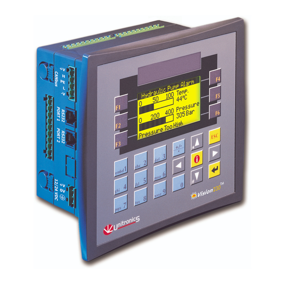
This guide provides basic information for Unitronics' Models V230/260/280/290 (Non-color Screens).
General Description
Vision OPLCs are programmable logic controllers that comprise an integral operating panel
containing a graphic LCD screen and a keyboard. All models offer the same PLC features.
Operating panel features differ according to model.
V230
LCD + Keyboard
Communications
I/O Options
Information Mode
Programming
Software,
& Utilities
Unitronics
V260
LCD + Keyboard
 2 serial ports: RS232 (COM1), RS232/RS485 (COM2)
 1 CANbus port
 The user can order and install an additional port. Available port
types are: RS232/RS485, and Ethernet
 Communication Function Blocks include: SMS, GPRS, MODBUS
serial/IP Protocol FB enables PLC to communicate with almost
any external device, via serial or Ethernet communications
Vision supports digital, high-speed, analog, weight and temperature
measurement I/Os via:
 Snap-in I/O Modules
Plug into the back of the controller to provide an on-board I/O
configuration
 I/O Expansion Modules
Local or remote I/Os may be added via expansion port or CANbus
This mode enables you to:
 View & Edit operand values, COM port settings, RTC and screen
contrast/brightness settings
 Calibrate the touchscreen
 Stop, initialize, and reset the PLC
To enter Information Mode, press the <i> button for several seconds.
The Unitronics Setup CD contains VisiLogic freeware and other utilities
 VisiLogic
Easily configure hardware and write both HMI and Ladder control
applications; the Function Block library simplifies complex tasks
such as PID. Write your application, and then download it to the
controller via the programming cable included in the kit
 Utilities
These include UniOPC server, Remote Access for remote
programming and diagnostics, and DataXport for run-time data logging
To learn how to use and program the controller, as well as use utilities such
as Remote Access, refer to the VisiLogic Help system.
Installation Guide
Models V230/260/280/290 (Non-color Screens)
V280
Touchscreen + Keyboard
V290
Touchscreen only
1

Advertisement

Table of Contents
loading
Need help?

Need help?

Do you have a question about the Vision 230 and is the answer not in the manual?

Questions and answers

Summary of Contents for Unitronics Vision 230

  • Page 1 Vision™ OPLC™ Installation Guide Models V230/260/280/290 (Non-color Screens) This guide provides basic information for Unitronics’ Models V230/260/280/290 (Non-color Screens). General Description Vision OPLCs are programmable logic controllers that comprise an integral operating panel containing a graphic LCD screen and a keyboard. All models offer the same PLC features.
  • Page 2: Kit Contents

    All examples and diagrams are intended to aid understanding, and do not guarantee operation  Unitronics accepts no responsibility for actual use of this product based on these examples Please dispose of this product according to local and national standards and regulations ...
  • Page 3 Installation Guide Mounting Dimensions V230 V260/280/290 Unitronics...
  • Page 4  To minimize electromagnetic interference, mount the controller on a metal panel and earth the power supply according to the details on page 5 1. Make a panel cut-out that suits your model controller. V230 Cut-out Dimensions V260/280/290 Cut-out Dimensions Unitronics...
  • Page 5: W Iring: General

     To avoid damaging the wire, do not exceed a maximum torque of 0.5 N·m  (5 kgf·cm) Caution Do not use tin, solder, or any substance on stripped wire that might cause the wire  strand to break Unitronics...
  • Page 6: Wiring Guidelines

    Signals are related to the controller’s 0V; this is the same 0V used by the power  supply Always use the appropriate port adapters  Caution The serial ports are not isolated. If the controller is used with a non-isolated external  device, avoid potential voltage that exceeds ± 10V Unitronics...
  • Page 7: Serial Communications

     Before you begin, touch a grounded object to discharge any electrostatic charge  Before removing a Snap-in I/O Module or opening the controller, you must turn off the power RS232/RS485 Jumper Settings Jumper RS232* RS485 RS485 Termination *Default factory setting. Unitronics...
  • Page 8 1. Line the circular guidelines on the controller up with the guidelines on the Snap-in I/O Module as shown below. 2 Apply even pressure on all 4 corners until you hear a distinct ‘click’. The module is now installed. Check that all sides and corners are correctly aligned. Unitronics...
  • Page 9 CAN protocols: Circuit protection  CANopen: 127 controllers or external device devices  Unitronics’ proprietary UniCAN: 60 terminating resistor controllers, (512 data bytes per scan) The CANbus port is galvanically isolated. CANbus Wiring Use twisted-pair cable. DeviceNet® thick shielded twisted pair cable is recommended.

This manual is also suitable for:

Vision 260Vision 280Vision 290

Table of Contents