Table of Contents
Advertisement
Quick Links
UniStream™ CPU-for-Panel
Unitronics' UniStream™ platform comprises control devices that provide robust, flexible
solutions for industrial automation.
This guide provides basic installation information for the UniStream™ CPU-for-Panel.
Technical specifications may be downloaded from the Unitronics website.
The UniStream™ platform
comprises CPU controllers, HMI
panels, and local I/O modules
that snap together to form an
all-in-one Programmable Logic
Controller (PLC).
Expand the I/O configuration
using a Local Expansion Kit or
remotely via CANbus.
CPU-for-Panel
HMI Panels
Available in
different
dimensions
I/O Options
Programming
Software
Use of this product is subject to a Unitronics Controller License Agreement, a copy of which can be found at
Unitronics
CPUs are Programmable Logic Controllers (PLCs), the heart of the
UniStream™ platform.
The CPU-for-Panel cannot operate independently. It must be plugged
into the back of a UniStream™ HMI panel. The panel provides the CPU's
power source. The CPU-for-Panel comprises:
IO/COM Bus connector for interfacing Uni-I/O™ & Uni-COM™ modules
Isolated RS485 and CANbus ports
Backup battery
A high-resolution touch screen provides the operator interface for the
system and the physical foundation for a PLC+HMI+I/Os all-in-one
controller.
The DIN-rail structure on the panel's back is designed to physically
support a CPU-for-Panel controller, Uni-I/O™ and/or Uni-COM™
modules.
Each panel comprises:
AUX connector to support the CPU
1 audio-out 3.5mm jack
1 microSD slot
2 type A, USB host ports and 1 Mini-B USB device port
2 Ethernet ports, RJ45, 10/100 Mbps
1 power input connector, 12/24 VDC
Integrate I/Os into your system by using:
On-board I/Os: snap onto the panel for an all-in-one configuration
Local I/O via a Local Expansion Kit
Remote I/O via EX-RC1
All-in-one UniLogic™ software, for hardware configuration,
communications, and HMI/PLC applications, available as a free
download from Unitronics web site.
Installation Guide
USC-P-B10
http://unitronics.com/unistream/Agreements/UniLic1.pdf
1
Advertisement
Table of Contents

Related Manuals for Unitronics UniStream


Summary of Contents for Unitronics UniStream
- Page 1 All-in-one UniLogic™ software, for hardware configuration, Software communications, and HMI/PLC applications, available as a free download from Unitronics web site. Use of this product is subject to a Unitronics Controller License Agreement, a copy of which can be found at http://unitronics.com/unistream/Agreements/UniLic1.pdf Unitronics...
-
Page 2: Before You Begin
Use caution. All examples and diagrams are intended to aid understanding, and do not guarantee operation. Unitronics accepts no responsibility for actual use of this product based on these examples. Please dispose of this product according to local and national standards and regulations. -
Page 3: Kit Contents
UniStream™ Kit Contents 1 CPU-for-Panel 1 CANbus terminal block 1 lithium battery, 3V, CR2032. 1 CANbus termination resistor The battery is installed; pull out plastic tab 1 set of module numbering stickers. to activate it. -
Page 4: Cpu-For-Panel Mechanical Dimensions
Battery Replacement Use proper precautions to prevent Electro-Static Discharge (ESD) while servicing the battery. Caution To preserve back-up values for RTC and system data during battery replacement, the CPU-for-Panel must be powered from the HMI Panel. Unitronics... -
Page 5: Installation
UniStream™ 1. Open the CPU door and remove the battery cover. 2. Remove the used battery and insert the new one, ensuring that the polarity is aligned with the polarity drawing as shown in the accompanying figure. 3. Replace the battery cover. -
Page 6: About The Cpu's Io/Com Bus Connector
Use a metal cabinet. Make sure the cabinet and its doors are properly earthed. Use wires that are properly sized for the load. For detailed information, refer to the document System Wiring Guidelines, located in the Technical Library in the Unitronics’ website. Unitronics... -
Page 7: Communication Ports
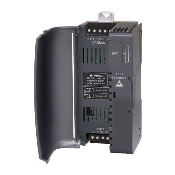
UniStream™ Communication Ports Turn off power before making any communications connections. RS485 Use the RS485 port to create a multi-drop network. The CPU-for-Panel is shipped with a 4 pin RS485 terminal block. This connector is marked with a pin assignment that is identical to the corresponding marking on the CPU-for-Panel. - Page 8 CPU-for-Panel Installation Guide CANbus Use the CANbus port for all CANbus communications including integration of Remote I/Os via EX-RC1. The CPU-for-Panel is shipped with a 5 pin CANbus terminal block. This connector is marked with a pin assignment that is identical to the corresponding marking on the CPU- for-Panel.
Need help?
Do you have a question about the UniStream and is the answer not in the manual?
Questions and answers