Advertisement
Important: Read all instructions prior to installation.
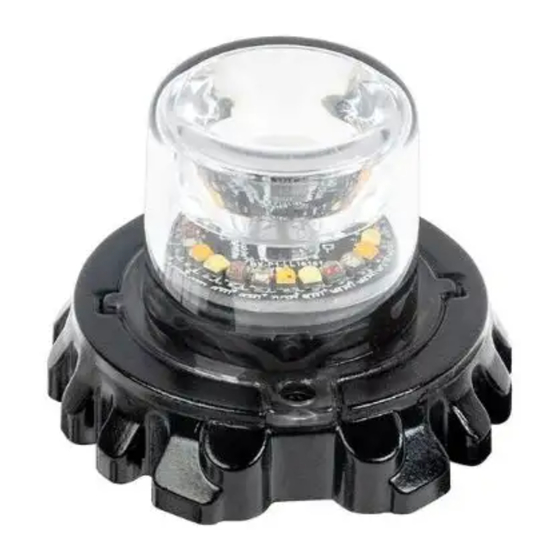
Hideaway LED Strobe
Safety and Notes
Please read all of the following instructions before installation. Failure to install or use this product according to the manufacturer's
recommendations may result in property damage, serious injury, and/or death.
• Proper installation of the product requires the installer to have a good understanding of automotive electronics, systems, and procedures.
• This product contains high-intensity LEDs. Do not stare directly into these lights. Momentary blindness and/or eye damage could result.
• Use only soap and water to clean the outer lens.
• Do not install this product or route any wires in the deployment area for your air bag. Equipment mounted or located in the air bag deployment area
will damage or reduce the effectiveness of the air bag, or become a projectile that could cause serious personal injury or death. Refer to your vehicle
owner manual for the air bag deployment area. The User/Installer assumes full responsibility to determine proper mounting location, based on providing
ultimate safety to all passengers inside the vehicle.
• If mounting this product requires drilling holes, the installer must be sure that no vehicle components or other vital parts could be damaged by the drilling
process. Check both sides of the mounting surface before drilling begins. Also de-burr any holes and remove any metal shards or remnants. Install
grommets into all wire passage holes.
• Inspect and operate this product regularly to confirm its proper operation and mounting condition. Do not use a pressure washer to clean this product.
• For this product to operate at optimum efficiency, a good electrical connection to the chassis ground must be made. The recommended procedure
requires the product ground wire to be connected directly to the NEGATIVE (-) battery post.
• It is recommended that these instructions be stored in a safe place and referred to when performing maintenance and/or re-installation of this product.
Operation
Connections:
Wire
Group 1
Red
Positive
White
Black
Negative
Blue
Apply to negative for pattern switch
apply to positive for dimming
Yellow
Synchronized Function
Green
Apply to negative for mode switch
Pattern Switch Operation:
Blue wire applies to Negative to Switch Flash Pattern
- Less than 1 second: Next Pattern
- Between 1-3 seconds: Previous Pattern
- Between 3-5 seconds: Factor Default Pattern
- More than 5 seconds: Last Pattern
Phase Operation
- Phase 1 (Ph1) flashes simultaneously with Phase 1 (Ph1).
- Phase 2 (Ph2) flashes simultaneously with Phase 2 (Ph2).
- Phase 1 (Ph1) flashes alternates with Phase 2 (Ph2).
Troubleshooting
The Light Head has been factory tested and approved. If the functions of the device fail, please check the following:
1. After connecting with the power supply, be sure that the power source end is joined in the correct way. And then, make sure that there
is no short-circuited power occurring. Plug device ensure the power switch which has LED is "ON" state.
2. Ensure the Power switch is turned to the "ON" position.
Quad Color
Group 2
Group 3
Positive
Positive
Positive
Mode Switch Operation: Apply Green Wire to Negative.
Mode 1
Color 1
Mode 2
Color 2
Mode 3
Color 3
Mode 4
Color 4
Mode 5
Color 1 & 2
Mode 6
Color 1 & 3
Mode 7
Color 1 & 4
Mode 8
Color 2 & 3
Recommend Operation Environment
Ambient Temperature: -22°–122° F (-30°–50° C)
Relative Humidity: 10–85%, non-condensing
Setting Synchronization
- Set all lights to the same Flash Pattern, then connect the
Yellow wire of all lights together for synchronization.
- Maximum of 8 Warning Lights can be synchronized.
Rev Date: V1 11/28/2022
4400 Earth City Expy, St. Louis, MO 63045
User Manual
MSTRB2
Quad Color
Mode 9
Color 2,4
Mode 10
Color 3,4
Mode 11
Color 1,2,3
Mode 12
Color 1,2,4
Mode 13
Color 1,3,4
Mode 14
Color 2,3,4
Mode 15
Color 1,2,3,4
866-590-3533
superbrightleds.com
Advertisement
Table of Contents

Related Manuals for superbrightleds MSTRB2


Summary of Contents for superbrightleds MSTRB2
- Page 1 User Manual MSTRB2 Important: Read all instructions prior to installation. Hideaway LED Strobe Safety and Notes Please read all of the following instructions before installation. Failure to install or use this product according to the manufacturer’s recommendations may result in property damage, serious injury, and/or death.
- Page 2 MSTRB2 Type Quad Color Pattern Sync Mode Single 75FPM Ph1 Color 1 Single 75FPM Ph2 Color 1 Single 75FPM Ph1 Color 2 Single 75FPM Ph2 Color 2 Single 75FPM Ph1 Color 3 Single 75FPM Ph2 Color 3 Single 75FPM Ph1 Color 4...
- Page 3 MSTRB2 Type Quad Color Pattern Sync Mode Double 120FPM Ph1 Color 1 Double 120FPM Ph2 Color 1 Double 120FPM Ph1 Color 2 Double 120FPM Ph2 Color 2 Double 120FPM Ph1 Color 3 Double 120FPM Ph2 Color 3 Double 120FPM Ph1 Color 4...
- Page 4 MSTRB2 Type Quad Color Pattern Sync Mode NFPA-Quad Flash 90FPM Color 1 NFPA-Quad Flash 90FPM Color 2 NFPA-Quad Flash 90FPM Color 3 NFPA-Quad Flash 90FPM Color 4 ModuFlash sim. Color 1 ModuFlash sim. Color 2 ModuFlash sim. Color 3 ModuFlash sim. Color 4...
Need help?
Do you have a question about the MSTRB2 and is the answer not in the manual?
Questions and answers