Advertisement
Quick Links
Important: Read all instructions prior to installation.
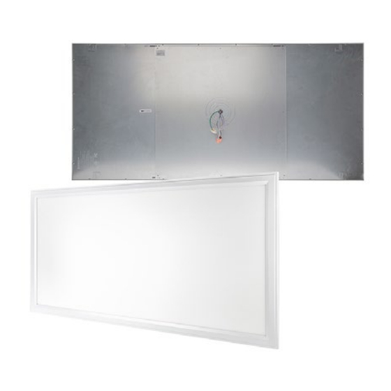
LED Dimmable Panel Light
LPD-40K24-40-SMK
Specifications
ALLA TION
Operating Temperature
IP Rating
Weight
Same to 4 hang buckles.(Figure 2)
Recessed Installation
Note: Recessed Mounting Kit
Required (LPD-JBK)
1. Turn off power and remove
existing fixture or remove ceiling tile.
2. Bend each t-bar safety hook away
from panel until facing perpendicular
to panel backing. Bend hook arm
until facing perpendicular to hook
body. (Fig. 2 & 3)
3. Remove the knockout hole on the
junction box. Run wiring through
hole and secure conduit. (Fig. 4)
Connect all wiring according to the
wiring diagram.
4. Attach junction box to panel backing by
inserting the tabs from the junction box into
the slots on the panel backing. Secure to the
panel with provided screw. (Fig. 5)
5. Place panel into T-grid, making sure it is
securely supported.
Step Dimming
RED
BLACK
PURPLE
FS SERIES
RECESSED INST
LPD-xK24-40
-4°–104° F (-20°–40° C)
16 lb 5oz (7.4 kg)
Figure1
Figure2
Figure3
Figure4
,
Figure5
Turn On
Lamp
Turn Off
After 0.5S
At 0.5-2s
Lamp
100%
brightness
Safety and Notes
• Product should be installed and serviced by a certified
electrician in accordance with applicable national, state, and
local building and electrical codes.
• To reduce the risk of electric shock, ensure that the main power
source and circuit breakers are switched off before performing
any installation or wiring procedures.
• Avoid looking directly into lamp when illuminated.
• Ensure all mounts are securely attached and will support the
weight of the fixture. Failure to properly support fixture may
result in damage or injury, for which the manufacturer does not
assume responsibility.
ALLA TION
LPD-xK22-40
LPD-xK14-40
IP20
8 lb 2oz (3.7 kg)
8 lb 12oz (4 kg)
Mounting Options
Recessed Mounting Kit (LPD-JBK)
sold separately
1 - Junction Box
1 - Attachment Screw
Surface Mounting Kit (LPD-SMK24, LPD-SMK22, LPD-SMK14)
sold separately
1 - Surface Mount Bracket
7 - Screws
7 - Screw Anchors
1 - Cable Service Loop
1 - Cable Service Loop Screw
Wiring Diagram
WIRING DIAGRAM
0-10V
Dimmer
Rev Date: V2.0 10/27/2021
4400 Earth City Expy, St. Louis, MO 63045
Turn On
Lamp
50%
brightness
User Manual
LPD Series
Check product label for specific electrical
specifications related to installation.
Improper installation will void warranty.
PURPLE
PURPLE
D +
GREY
GREY
D -
LINE
BLACK
NEUTRAL
WHITE
GREEN
GROUND
866-590-3533
FS SERIES
Surface Mounted
S te p1: Remove the
from the luminaire.
1
S tep3: Align the holes o
the hole on the J-box Ti
the plate to your right po
screws into the ceiling a
the ceiling.
3
LED
PANEL
S te p5: Fix the metal
(Fig.2)
superbrightleds.com
5
Advertisement

Subscribe to Our Youtube Channel
Related Manuals for superbrightleds LPD Series


Summary of Contents for superbrightleds LPD Series
- Page 1 User Manual LPD Series Important: Read all instructions prior to installation. LED Dimmable Panel Light Safety and Notes • Product should be installed and serviced by a certified electrician in accordance with applicable national, state, and local building and electrical codes.
- Page 2 J-box into the male connector. from the luminaire. of the J-box into the male connector. User Manual LPD Series Important: Read all instructions prior to installation. LED Dimmable Panel Light Surface Mount Kit Installation FS SERIES 2.
Need help?
Do you have a question about the LPD Series and is the answer not in the manual?
Questions and answers