Table of Contents
Advertisement
Quick Links
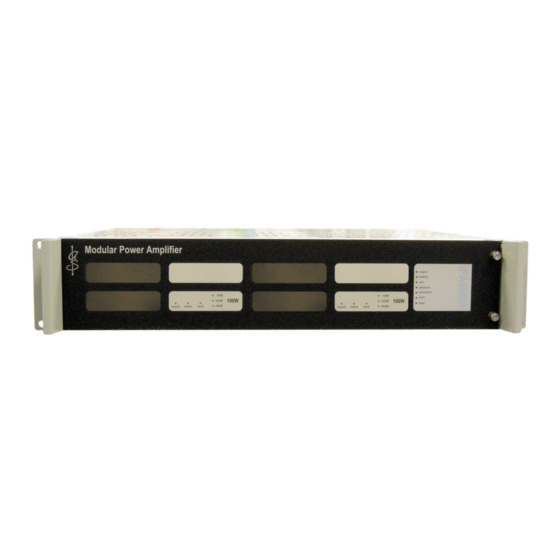
Intelligent 400 W PA Amplifier Mainframe with Amplifier
and Loudspeaker Line Monitoring
Product Manual
ASL Document Ref.: U-0629-0171.doc
Issue: 04 complete, approved - Date: 29/04/10
iPAM400
(Audio I/O Expansion Module is optional and shown for illustrative purposes.)
iPAM400 fitted with
2 x MX200 Amplifier Modules for
illustrative purposes.
Advertisement
Table of Contents

Subscribe to Our Youtube Channel
Related Manuals for ASL INTERCOM iPAM400


Summary of Contents for ASL INTERCOM iPAM400
- Page 1 Intelligent 400 W PA Amplifier Mainframe with Amplifier and Loudspeaker Line Monitoring iPAM400 fitted with 2 x MX200 Amplifier Modules for illustrative purposes. (Audio I/O Expansion Module is optional and shown for illustrative purposes.) Product Manual ASL Document Ref.: U-0629-0171.doc...
- Page 2 – Product Manual This equipment is designed and manufactured to conform to the following EC standards: EMC: EN61000-6-4:2007, EN61000-6-2:2005, EN55103-1/E1:1996, EN55103-2/E5:1996, EN50121-4:2006, ENV50204:1995 Safety: EN60065:2002 Failure to use the equipment in the manner described in the product literature will invalidate the warranty.
-
Page 3: Table Of Contents
– Product Manual Contents Overview ..............................7 Functional Description ..........................10 Controller ..........................11 2.1.1 External Interfaces......................11 2.1.2 VIPA Software Functionality ....................11 2.1.2.1 IP Connectivity......................11 2.1.2.2 Audio Broadcasts ....................12 2.1.2.2.1 PC/DVA (PC based Digital Voice Announcer) ..........12 2.1.2.2.2 Local Paging Microphone................12 2.1.2.2.3 Local Paging from Other Equipment ............12... - Page 4 Playing a 1 kHz Test Tone to an iPAM400 Local Output........75 6.3.1.5.2 Playing Pink Noise to an iPAM400 Local Output...........76 6.3.1.5.3 Playing a 1 kHz Tone and Pink Noise to an iPAM400 Local Output ....77 6.3.1.5.4 Playing the Built-in Test Message to an iPAM400 Local Output....78 6.3.1.5.5 Playing the Built-in Test Message to a Configured Zone......79...
- Page 5 Restarting the iPAM400 Software ................81 6.3.1.6.1 Restarting the iPAM400 Software With Event Logging Disabled....81 6.3.1.6.2 Restarting the iPAM400 Software With Event Logging Enabled ....81 6.3.1.7 Copying Log and Configuration Files to a USB Memory Stick.........82 6.3.1.8 Deleting Log Files ....................82 6.3.1.9...
- Page 6 – Product Manual 12.5 Cabling.............................130 12.6 EMC ............................130 12.7 Ground Loops ..........................130 12.8 Lithium Battery ........................130 12.9 Unpacking and Handling ......................131 12.10 Packing for Return for Repair ....................131 Reference Documents ..........................132 Abbreviations............................133 Index ...............................135 U-0629-0171.doc – Issue: 04 complete, approved...
-
Page 7: Overview
The iPAM400 is designed to use the MX Series Amplifier Modules, and is not compatible with the M100, M200, and M400 M Series Amplifier Modules. These two series of amplifier modules are electrically identical, but have different mechanics and connectors. - Page 8 Each iPAM400 is a self-sufficient VIPA unit with local intelligence and can be configured to run as stand- alone unit or in a network. The iPAM400 supports full peer-to-peer IP communications for both voice and control.
- Page 9 – Product Manual Figure 1 System context example PC/DVA System (Customer Information System) PAGING MICROPHONE IP NETWORK iPAM400 BMB01 MONITOR/ MOUSE/ Remote I/O Unit KEYBOARD PAGING MICROPHONE (Ambient Noise Sensor LOUDSPEAKER CIRCUITS iPAM400 iPAM400 PAGING (Background Music) MICROPHONES LOUDSPEAKER...
-
Page 10: Functional Description
– Product Manual Functional Description The iPAM400 is functionally split into four main blocks as shown in Figure 2. Figure 2 iPAM400 block diagram iPAM400 AUX AUDIO IN AUDIO IN (ASL PAGING ETHERNET MICROPHONE OR AUDIO IN OTHER SOURCE) -
Page 11: Controller
PC/DVA System, other PC/DVA system, or a Customer Information System (CIS). The transmission of audio between the iPAM400 and other VIPA units such as the VIPET IP Audio Controller and the iPA400 Amplifier Mainframe uses PMC (Portable Media Carrier) protocol capable of multicast operation where there is one source and multiple simultaneous destinations. -
Page 12: Audio Broadcasts
Line PA) systems. 2.1.2.2.4 OGG File Playback The iPAM400 can receive an OGG Vorbis encoded audio file with sampling frequency from 22 kHz to 48 kHz, decompress it at 10 x real-time speed, and play it into any combination of amplifiers. 2.1.2.2.5... -
Page 13: Surveillance Tone Generation
2.1.2.8 BMB01 Remote I/O Unit The input ports which are used for connection of ASL microphones to the iPAM400 are also fully compatible with the ASL BMB01 Remote I/O Unit. The BMB01 provides twelve analogue inputs, twelve digital inputs, and twelve digital outputs. -
Page 14: Bmb01 Analogue Inputs
Non-Monitored Contact BMB01 Simple contact closure. ANALOGUE INPUT (1 TO 12) CABLING TO CONTACT Non-monitored contact is not implemented in the iPAM400 application at the time of publication of this document. U-0629-0171.doc – Issue: 04 complete, approved Page 14 of 138... -
Page 15: Bmb01 Digital Outputs
– Product Manual +5 V Monitored Contact 4k7 ohms This interface enables the iPAM400 to monitor the AL 1 - 12 interface to the contact closure. The contact must be fitted with 6k8/470R resistors. 470 ohms BMB01 A resistance of 7270 ohms indicates inactive (switch... -
Page 16: Amplifier Motherboard
Auxiliary Power Supply Output The iPAM400 provides an auxiliary supply output (21 V to 38 V) which can be used to supply other pieces of equipment up to a limit of 1 A. This supply output is derived from the mains and battery supplies. The auxiliary power supply output and the integrity of the auxiliary supply fuse are monitored and indicated via a front panel LED. -
Page 17: Amplifier Modules
• MX400 400 W Amplifier Module The MX100, MX200, and MX400 amplifier modules respectively occupy one, two or four slots in the iPAM400 mainframe. A front fascia panel is fitted to the mainframe to provide protection for the amplifier module(s) and annotations for the LED indicators. -
Page 18: Loudspeaker Line Monitoring Using Dc Surveillance
2) The iPAM400 temporarily superimposes a continuous surveillance tone on its outputs when requested by the amplifier motherboard. This happens during the fault diagnostic process. When the amplifier motherboard detects a fault, it requests the iPAM400 to superimpose a continuous surveillance tone on the required output for the duration of the diagnostic process in order to be able to isolate the faulty lines quickly. - Page 19 – Product Manual Figure 4 Loudspeaker lines using DC surveillance EOL10K CIRCUIT C = DC BLOCKING CAPACITOR iPAM400 SPUR AMPLIFIER SLOT 1 OUTPUT 'A' EOL10K OUTPUT 'B' EOL10K OUTPUT 'C' EOL10K EOL10K EOL10K CIRCUIT CIRCUIT SPUR SPUR OUTPUT 'D'...
-
Page 20: Line Open Circuit Fault
– Product Manual 2.4.3.1.1 Line Open Circuit Fault The system reports a line open circuit fault when the DC surveillance indicates that the total number of spurs has decreased below the commissioned value for the amplifier. The total number of spurs is the sum of spurs commissioned for the amplifier slot. -
Page 21: Dc Blocking Capacitor Values
– Product Manual 2.4.3.2 DC Blocking Capacitor Values All loudspeakers connected to the system must be fitted with DC blocking capacitors. Loudspeakers are available with suitable capacitors pre-installed from a variety of suppliers. Alternatively, DC blocking capacitors may be retrofitted. -
Page 22: Loudspeaker Line Earth Leakage Monitoring
The iPAM400 reports its current announcement and fault status via a JCOP/JPC interface over TCP/IP to the control system, which can then provide the appropriate indication to the user. The iPAM400 uses the same method to report the status of any external fault inputs connected to a BMB01 Remote I/O Unit; see Section “2.1.2.8 BMB01 Remote I/O Unit”... -
Page 23: Controls And Indicators
-20dB -20dB fault -40dB -40dB supply select fault supply select fault (iPAM400 fitted with two MX200 200 W Amplifier Modules as example.) DETAIL WITHOUT FRONT PANEL: RESET/SHUT DOWN BUTTON BATTERY ISOLATION SWITCH MAINS ISOLATION SWITCH MAINFRAME ADDRESS SWITCHES U-0629-0171.doc – Issue: 04 complete, approved... - Page 24 Green LED Illuminates to indicate that the Ethernet connection is operational. Flashes slowly to indicate that the iPAM400 is operational, i.e., both the Controller and the Amplifier Motherboard processors are operational. Flashes fast to indicate that the iPAM400 application is not running.
-
Page 25: Rear Panel Indicators And Controls
Press of > 5 seconds at any time Causes an instant iPAM400 application power-down. It is recommended that the iPAM400 application be shut down using the Reset/Shut Down button before power is disconnected from the iPAM400 using the mains and battery isolation switches. - Page 26 – Product Manual Mainframe Controls Control Function The Earth Lift switch is provided to allow removal of the mains earth from the signal circuits. This may be required in order to eliminate ground loops between connected equipment. Possible settings: DOWN (...
-
Page 27: Installation
MX200 200 W Amplifier Modules shown as an example: one fitted into the iPAM400 mainframe and one outside it. The lid is supplied fitted, and is not normally removed. It is only shown removed here in order to enable the iPAM400’s internal construction to be seen. -
Page 28: Installation Requirement
2) The supporting rails must be capable of safely bearing the weight of the equipment (max. 20 kg). If the iPAM400 is intended to be table or shelf mounted, i.e. not in a 19-inch standard rack, then the unit should always be fitted into a 19-inch desk case or flight case. This is to prevent ingress of dust or debris that may otherwise occur over a period of time. -
Page 29: External Cabling Requirements
13-way screw-in terminal block multicore, screened • Digital outouts: multicore, screened ANS is connected to a BMB01 unit, with no direct connection to the iPAM400. • ANS side: Suitably rated foil screened 3- ANS Sensor 1 x 3-core, screened Screw-in terminal block core cable •... -
Page 30: Recommended Installation Procedure
Figure 6. 1) If the iPAM400 is intended to be table or shelf mounted, i.e. not in a 19-inch standard rack, then the unit should always be fitted into a 19-inch desk case or flight case. - Page 31 – Product Manual If fitted, then remove the iPAM400 front panel by undoing the two captive M3 Pozidriv screws on the right side of the front panel. If a MX400 amplifier module is used and the loudspeaker line monitoring is performed using AC surveillance with AEL01 or AEL02 Active End of Line Device, then the link setting on the amplifier module needs to be adjusted as shown in Figure 7.
- Page 32 – Product Manual Figure 8 Installing the amplifier modules into the iPAM400 MX200 MODULE SIDE PANELS MUST LOCATE IN MAINFRAME SLIDES (1 x MX200 shown as example.) MX200 STANDARD CONFIGURATIONS: 4 x MX100 CONFIGURATION 1 x 200 W + 2 x 100 W CONFIGURATION...
- Page 33 – Product Manual If the rack is to be transported, then secure the amplifier modules to each other and to the mainframe sides using transit screws; see Figure 9. Do not transport partially equipped mainframes. Either remove all amplifier modules, or fix all modules in a fully populated mainframe using transit screws.
- Page 34 – Product Manual Figure 10 Setting the Earth Lift switch and the Mode DIP switches EARTH LIFT DOWN ‘Mode’ DIP Switch Settings Switch No. Switch Name Function when ON (down position) Function when OFF (up position) For ASL use only (for software debug Debug Always set this switch to OFF.
- Page 35 – Product Manual Connect the field wiring as required; see Figure 12. Figure 12 Connecting the field wiring AUDIO I/O EXPANSION MODULE (OPTIONAL) AUDIO INPUTS NOT USED LOW LEVEL AUDIO OUTPUTS ETHERNET AUDIO IN/RS485 PORTS RS232 SLOT 4 SLOT 3...
- Page 36 – Product Manual Connect the AC mains power supply cable, and secure it with the retaining clip; see Figure 13. Always ensure that the equipment is correctly earthed by connection to an AC mains supply with a protective earthing connection.
- Page 37 Once the front panel is fitted, the power ON/OFF switch and the Reset/Shut Down button will not be accessible. Fit the amplifier mainframe panel by sliding its left end under the left iPAM400 handle, and fixing its right end using the two captive M3 Pozidriv screws; see Figure 14.
- Page 38 – Product Manual 4 x 100 W FRONT PANEL Modular Power Amplifier mains battery ethernet processor -0dB -0dB -0dB -0dB sync 100W 100W 100W 100W -20dB -20dB -20dB -20dB fault supply select fault -40dB supply select fault -40dB supply...
-
Page 39: Connections
– Product Manual Connections Figure 15 iPAM400 connection points iPAM400 – FRONT (FRONT PANEL REMOVED) AUDIO I/O EXPANSION MODULE (OPTIONAL) AUDIO INPUTS NOT USED The rear RS232 PORT is also duplicated on the LOW LEVEL AUDIO OUTPUTS front of the... - Page 40 – Product Manual U-0629-0171.doc – Issue: 04 complete, approved Page 40 of 138...
-
Page 41: Terminal Allocation
– Product Manual Terminal Allocation All connector views looking into the rear of the iPAM400. 5.1.1 AC Mains Inlet Signal Description Live (European standard: 230 V, 50 Hz, +/–10%) IEC320 plug Earth L E N Neutral (European standard: 230 V, 50 Hz, +/–10%) 5.1.2... -
Page 42: Line Standby Input: Standby In
– Product Manual 5.1.4 100 V Line Standby Input: STANDBY IN Signal Description 2 x 2-way pluggable − 100 V line audio circuit from standby amplifier Wago cage clamp terminal As above (5.08 mm) (male) Ensure +/- phase is preserved. -
Page 43: Audio-Can Bus / Rs485 Port: Status Ports
– Product Manual 5.1.7 Audio-CAN Bus / RS485 Port: STATUS PORTS Pin No Signal Description Data– RS485DXN (EIA RS485 9600 baud) FEMALE Controller Area Network CAN_L (Low) 0 V Reference Audio Monitor Bus AUDIO MON- –10 dBu nominal AUDIO MON+... -
Page 44: Ethernet Port
– Product Manual 5.1.9 Ethernet Port Pin No Description Transmit+ Transmit− Receive+ Receive− RJ45 jack 4, 5, 7, 8 Unused 5.1.10 USB Ports 1 and 2 1 2 3 4 Pin No Signal Description VBUS + V Supply (output) USB type A socket D−... -
Page 45: Audio I/O Expansion Module Inputs And Outputs (Optional)
(3.81 mm) − As above but –ve level (male) These outputs are paralleled with the iPAM400’s internal audio feeds to the amplifier slots in each slot and can be used to feed external expansion amplifiers. U-0629-0171.doc – Issue: 04 complete, approved... -
Page 46: Connection Diagrams
The following diagrams show examples of the connection of an ASL BMB01 Remote I/O Unit, ANS Sensors, and Paging Microphones to the iPAM400. 5.2.1 Microphone Connection The following diagrams show examples of connection of ASL microphones to the iPAM400: • DMS Paging Microphone: see Figure 16 (page 46). •... - Page 47 – Product Manual Figure 17 SAP02 Station Announcement Point connection iPAM400 SAP02 ENCLOSURE INPUT 1 INPUT 2 SCRN GROUND AUDIO+ AUDIO- 0V SUPPLY +V SUPPLY MIC DATA DXP MIC DATA DXN GROUND SCRN COMMISSIONING DATA DXP COMMISSIONING DATA DXN...
-
Page 48: Bmb01 Remote I/O Connections
– Product Manual 5.2.2 BMB01 Remote I/O Connections The iPAM400 supports the connection of the ASL BMB01 Remote I/O Unit as described in the following sections. 1) The iPAM400 can support up to nine BMB01 units. 2) An iPAM400 input port can be used for simultaneous connection of the serial interface of a BMB01 unit, and of an audio source that does not require data connections, such as background music. -
Page 49: Bmb01 And Ans Sensor Connection
– Product Manual 5.2.2.1 BMB01 and ANS Sensor Connection Figure 19 BMB01 connection to ANS (example) iPAM400 BMB01 INPUT 1 LOCAL INPUT 2 ISOLATED SUPPLY BMB01 POWERED BY EXTERNAL POWER SCRN SUPPLY (ALTERNATIVE TO POWER FROM iPAM400 SHOWN BELOW) - Page 50 5) ANS sensors can be configured on different BMB01 units. Up to twelve ANS sensors can be configured on each BMB01 unit. Any number of ANS sensors configured on the iPAM400 can be assigned for each amplifier. Notes (Figure 19): 1) The Auxiliary DC Output (AUX OUT) can alternatively be used to power the BMB01.
-
Page 51: Bmb01 And Routing Contact Interface Connection For Llpa/Cis
– Product Manual 5.2.2.2 BMB01 and Routing Contact Interface Connection for LLPA/CIS The BMB01 contact inputs and outputs can provide a digital handshaking interface to a LLPA or CIS system. Refer to Section “11 Appendix – Three Line LLPA Interface” (page 125) for further details. - Page 52 – Product Manual Warnings (Figure 20): 1) ACCESS REQUEST: Input “DI ” can be any of the available digital inputs of the BMB01 (DI1 to DI12). 2) BUSY: Output “DO ” can be any of the available digital outputs of the BMB01 (DO1 to DO12).
-
Page 53: Bmb01 And Monitored Fault Input Connection For Third-Party Equipment Fault Monitoring
– Product Manual 5.2.2.3 BMB01 and Monitored Fault Input Connection for Third-Party Equipment Fault Monitoring The BMB01 analogue inputs can be used for fault inputs from other equipment where the fault wiring is monitored by the iPAM400. Only the analogue inputs of the BMB01 can support resistively monitored fault inputs. - Page 54 – Product Manual Warnings (Figure 21): 1) The contacts must be fitted with 6k8/470R resistors. 2) Input “AI ” can be any of the available analogue inputs of the BMB01 (AlI1 to Al12). Notes (Figure 21): 1) The Auxiliary DC Output (AUX OUT) can alternatively be used to power the BMB01.
-
Page 55: Bmb01 And Non-Monitored Fault Input Connection For Third-Party Equipment Fault Monitoring
(Pin 52) SCREEN SCRN +24V0ut See Notes 2 and 3 (Pin 26) Non-monitored analogue input is not implemented in the iPAM400 application at the time of publication of this document. U-0629-0171.doc – Issue: 04 complete, approved Page 55 of 138... - Page 56 – Product Manual Warnings (Figure 22): 1) Input “AI ” can be any of the available analogue inputs of the BMB01 (AlI1 to Al12). 2) Input “DI ” can be any of the available digital inputs of the BMB01 (DI1 to DI12).
-
Page 57: Connection Of External Amplifiers
The low level outputs on the optional Audio I/O Expansion Module enables the connection of external amplifiers to the iPAM400; see example in Figure 23. These low level outputs are paralleled with the internal feeds to the amplifier slots and can be used to: 1) Add extra power to a zone by fitting an external amplifier in parallel. -
Page 58: Avoiding Ground Loop Problems
– Product Manual Avoiding Ground Loop Problems It is possible to form a ground loop when connecting pieces of audio equipment using unbalanced connections that provide alternative earth connections via their cable screens. Such ground loops result in audible ‘hum’ from the system. -
Page 59: Commissioning
Please refer to the VIPA Config Tool help for details. Connecting to the iPAM400 iPAM400 provides software tools such as the Setup Tool and commands which are run remotely from a host PC over the network or locally from a keyboard and monitor directly connected to the iPAM400. -
Page 60: Connecting Remotely Via Putty (For A Host Pc Running Windows)
Connecting Remotely via PuTTY (for a host PC running Windows) To Run PuTTY: iPAM400 hostname or IP address PuTTY can be run from a host PC running Windows. Power and start the iPAM400, if not already done. Run PuTTY by double clicking its EXE file. The “PuTTY Configuration” window will be displayed. -
Page 61: Connecting Remotely Via A Ssh (Secure Shell) Session (For A Host Pc Running Linux)
RSA key fingerprint is If this is the first time that you log into 53:b4:ad:c8:51:17:99:4b:c9:08:ac:c1:b6:05: this iPAM400, it will ask if you wish to 71:9b. add the remote host to a list of Are you sure you want to continue known_hosts. -
Page 62: Connecting Locally To The Rs232 Serial Port (Via Terminal Emulator)
6.2.3 Connecting Locally to the RS232 Serial Port (via Terminal Emulator) You will require a NULL modem cable and the iPAM400 passwords in order to connect to the iPAM400 via a Terminal Emulator connected to the serial port. Contact ASL Customer Care department to obtain the required passwords. -
Page 63: Connecting Locally Via A Monitor And Usb Keyboard
Connecting Locally via a Monitor and USB Keyboard To Connect to the iPAM400: (MONITOR) Connect the monitor and keyboard to the iPAM400 rear panel connectors. Power and start the iPAM400, if not already done. (KEYBOARD MEMORY STICK) The iPAM400 will prompt for login. -
Page 64: Setup Tool
The iPAM400’s built-in Setup Tool enables the user to configure the iPAM400 from a configuration file, either locally or remotely. It also enables the user to easily update the iPAM400 software. Additionally the Setup Tool provides test functions which can support the system commissioning and testing. -
Page 65: Getting The Software Build Version
To Get the Installed Software Build Version: Run the Setup Tool as follows, if not already running. Connect to the iPAM400 either remotely or locally, as described in Section “6.2 Connecting to the iPAM400” (page 59). Run the Setup Tool by entering the following command: /dva/bin/vipet_setup Choose the “Get software version”... -
Page 66: Updating Or Restoring The Software Version
– Product Manual 6.3.1.2 Updating or Restoring the Software Version Make sure that a copy of all iPAM400 software builds is stored in a safe place other than the iPAM400. 6.3.1.2.1 Updating or Restoring the Software Version Using a USB Memory Stick This option enables the software to be locally updated or restored using a USB memory stick. -
Page 67: Updating Or Restoring The Software Version Using The Ram Disk
If no further tasks are to be performed, then return to the main menu (if not already done) and enter “X” to exit the Setup Tool. You can use WinSCP (for Windows) or SCP (for Linux) for copying the files into the iPAM400 RAM Disk. Please refer to ASL for further details. -
Page 68: Restoring The Software Version Using The Build Directory
You can also do this by using a USB memory stick (“6.3.1.2.1 Updating or Restoring the Software Version Using a USB Memory Stick”, page 66), or the iPAM400 RAM Disk (“6.3.1.2.2 Updating or Restoring the Software Version Using the RAM Disk”, page 67). -
Page 69: Updating Or Restoring The Ipam400 System Configuration
“2008-09-01-ipam400-station-01.cfg”. 2) A copy of all iPAM400 system configuration files should be stored in a safe place other than the iPAM400. 3) Create a backup copy of the current configuration file as described in Section “6.3.1.4.3 Creating a Backup of the Current Configuration”... -
Page 70: Updating Or Restoring The System Configuration Using The Ram Disk
If no further tasks are to be performed, then return to the main menu (if not already done) and enter “X” to exit the Setup Tool. You can use WinSCP (for Windows) or SCP (for Linux) for copying the files into the iPAM400 RAM Disk. Please refer to ASL for further details. -
Page 71: Updating Or Restoring The System Configuration The Using The Configuration Directory
A list of all configuration files (*.cfg file) available in the configuration directory will be shown. Choose the required configuration by entering its option number. A list of iPAM400 units will be shown. The configuration file can contain the configuration of more than one iPAM400 unit. -
Page 72: Changing The System Setup
To Modify the IP Configuration: Run the Setup Tool as follows, if not already running. Connect to the iPAM400 either remotely or locally, as described in Section “6.2 Connecting to the iPAM400” (page 59). Run the Setup Tool by entering the following command: /dva/bin/vipet_setup Choose the “System Setup”... -
Page 73: Safeguarding The Alsa Audio Settings
To Safeguard the ALSA Audio Settings: Run the Setup Tool as follows, if not already running. Connect to the iPAM400 either remotely or locally, as described in Section “6.2 Connecting to the iPAM400” (page 59). Run the Setup Tool by entering the following command: /dva/bin/vipet_setup Choose the “System Setup”... -
Page 74: Creating A Backup Of The Current Configuration
To Create a Backup of the Current Configuration: Run the Setup Tool as follows, if not already running. Connect to the iPAM400 either remotely or locally, as described in Section “6.2 Connecting to the iPAM400” (page 59). Run the Setup Tool by entering the following command: /dva/bin/vipet_setup Choose the “System Setup”... -
Page 75: Playing Test Tones And Test Messages
6.3.1.5.1 Playing a 1 kHz Test Tone to an iPAM400 Local Output This option will cause the iPAM400 to play a 1 kHz test tone to one of its own local outputs for approximately 30 seconds. To Play a 1 kHz Test Tone to an Output for 30 Seconds: Run the Setup Tool as follows, if not already running. -
Page 76: Playing Pink Noise To An Ipam400 Local Output
6.3.1.5.2 Playing Pink Noise to an iPAM400 Local Output This option will cause the iPAM400 to play pink noise (“static”) to one of its own local outputs for approximately 30 seconds. To Play Pink Noise to an Output for 30 Seconds: Run the Setup Tool as follows, if not already running. -
Page 77: Playing A 1 Khz Tone And Pink Noise To An Ipam400 Local Output
Playing a 1 kHz Tone and Pink Noise to an iPAM400 Local Output This option will cause the iPAM400 to play a 1 kHz test tone followed by pink noise to one of its local outputs in a continuous repeating loop. -
Page 78: Playing The Built-In Test Message To An Ipam400 Local Output
6.3.1.5.4 Playing the Built-in Test Message to an iPAM400 Local Output This option will cause the iPAM400 to play the built-in test message to one of its own local outputs. To Play the Built-in Test Message to an Output: Run the Setup Tool as follows, if not already running. -
Page 79: Playing The Built-In Test Message To A Configured Zone
Playing the Built-in Test Message to a Configured Zone This option will cause the iPAM400 to play the built-in test message to a zone configured for the iPAM400. A zone can be either a local output or a remote output, for instance an output of another VIPA unit in the network. -
Page 80: Playing A Message Stored In A Usb Memory Stick To A Zone
Playing a Message Stored in a USB Memory Stick to a Zone This option will cause the iPAM400 to play a message that is stored in the root directory of a USB memory stick to a zone configured for the iPAM400. A zone can be either a local output or a remote output, for instance an output of another VIPA unit in the network. -
Page 81: Restarting The Ipam400 Software
To Restart the iPAM400 with Event Logging Disabled: Run the Setup Tool as follows, if not already running. Connect to the iPAM400 either remotely or locally, as described in Section “6.2 Connecting to the iPAM400” (page 59). Run the Setup Tool by entering the following command: /dva/bin/vipet_setup Choose the “Test”... -
Page 82: Copying Log And Configuration Files To A Usb Memory Stick
6.3.1.8 Deleting Log Files The log files in the RAM Disk (/dev/shm/ directory) are deleted every time the iPAM400 is restarted or rebooted. There may be situations where it is required to delete these files manually without interrupting the iPAM400 operation, for example when memory space is low. -
Page 83: Collating Dva Filenames To A Usb Memory Stick
Choose the “Collate DVA filenames to USB flash drive” by entering “3”. A directory named after the iPAM400 host name will be created in the root of the attached USB memory stick and a file named ‘msgs’ will be created in that directory. -
Page 84: Clearing The Amplifier Mainframe Configuration
To Clear the Amplifier Mainframe Configuration: Run the Setup Tool as follows, if not already running. Connect to the iPAM400 either remotely or locally, as described in Section “6.2 Connecting to the iPAM400” (page 59). Run the Setup Tool by entering the following command: /dva/bin/vipet_setup Choose the “X400”... -
Page 85: Rebooting The Ipam400
– Product Manual 6.3.1.11 Rebooting the iPAM400 This option causes the iPAM400 to soft reboot itself, i.e. to restart the iPAM400 under software control, without removing power. To Reboot the iPAM400: Run the Setup Tool as follows, if not already running. -
Page 86: Setup Tool Menu Structure
See Note 1). 4. Gateway address: Change the iPAM400’s default gateway current address address. See Note 1). 5. Accept (all Cause the iPAM400 to reconfigure the IP changes will be setup and restart its network services. committed See Note 2). immediately!) C. - Page 87 – Product Manual Menu 5. Test 1. Play 1k {output list} Play a 1 [kHz] test tone for approx. 30 tone seconds to a local output of the user's choosing. C. Cancel Return to previous menu. 2. Play pink {output list} Play pink noise (“static”) for approx.
-
Page 88: Audio Settings
ALSA (Advanced Linux Sound Architecture) settings are pre-configured and they do not normally require user adjustments. Refer to ASL for ALSA setup instructions, if required. The amplifier mainframe will be cleared completely and the iPAM400 will stop working. A manual configuration will be required. Refer to ASL for instructions. - Page 89 – Product Manual To modify the Audio Input Gain, enter the following command line: /dva/bin/vipa_audio_set --input --channel=<channel-num> --parameter=level --value=<new-value> <channel-num> Where: 0: ‘INPUT 1’ on rear panel 1: ‘INPUT 2’ on rear panel <new-value> −60 to 20 (dB) Example: The following command line sets Input 1 gain to –15 dB.
- Page 90 – Product Manual To modify the Audio Output Gain, enter the following command line: /dva/bin/vipa_audio_set -- output --channel=<channel-num> --parameter=level --value=<new-value> <channel-num> 0: ‘SLOT 1’ output on rear panel Where: 1: ‘SLOT 3’ output on rear panel 2: ‘SLOT 2’ output on rear panel 3: ‘SLOT 4’...
-
Page 91: Fault Finding
– Product Manual Fault Finding The iPAM400’s front panel indicators provide the system’s overall status indication; see Table 2 and Table 3. The rear panel Audio In/RS485 Port LEDs indicate the RS485 communication status, as shown in Table 4. - Page 92 The mainframe fault will also illuminate if the DIP SW4 is set to ON enabling the fault reporting. For iPAM400 with amplifier frame firmware version older than V1.1.0206 slow flashing indicates that the controller is not operational. U-0629-0171.doc – Issue: 04 complete, approved...
- Page 93 Remove the front panel; see Section “8.1 Removing the Front Panel” (page 99). Power cycle the iPAM400 by switching off the mainframe AC mains and battery isolation switches; see Sections “8.2 Powering the Mainframe Off” (page 100) and ; “8.5 Powering the Mainframe On”...
- Page 94 Suggested actions: Check fuse on iPAM400 amplifier motherboard; see Section “8.13.2 iPAM400 Internal Fuses” (page 112). Check fuse on amplifier module; see Section “8.13.3 MX Amplifier Module Internal Fuses” (page 113). Replace amplifier module; see Section “8.10 Amplifier Module Replacement” (page 107).
- Page 95 – Product Manual Table 5 describes the iPAM400 faults which are reported to any attached control system. The faults are listed together with their symptoms and suggested actions. These faults are reported by the iPAM400 via a JCOP/JPC interface over TCP/IP, together with other system status information.
- Page 96 Loss of audio from DVA DVA messages are Note: This fault is only applicable and sync LEDs is ASLPAVA.Vipet.DVAFault messages. corrupt (invalid when the iPAM400 has pre- turned ON checksum) installed DVA messages. The iPAM400 does not have NTP configured, NTP is Mainframe fault •...
- Page 97 – Product Manual Operational Fault Symptom Fault Description Other Indication JPC Item Path Suggested Action • A one of occurrence may be experienced due to EMI or No operational failure on transients. initial fault report. Loss of all • No action required if the unit...
- Page 98 – Product Manual Operational Fault Symptom Fault Description Other Indication JPC Item Path Suggested Action • If new configuration is correct, Loss of all loudspeaker circuit Different amplifier Mainframe fault ASLPAVA.Vipet. perform a Learn/Commissioning. functionality on a single fitted from that...
-
Page 99: Maintenance
– Product Manual Maintenance The iPAM400 should be tested with the PA (Public Address) system for correct operation, at maximum intervals of three months, and as part of the system maintenance schedule. There are no routine maintenance tasks for the iPAM400 except for operational testing. -
Page 100: Powering The Mainframe Off
– Product Manual Powering the Mainframe Off Check whether the iPAM400 application is running, by observing the processor LED on the mainframe front panel: BATTERY AND AC MAINS ISOLATION • flashing slowly: the iPAM400 application SWITCHES: OFF is running, then shut it down by briefly pressing the Reset/Shut Down button on the front panel. -
Page 101: Removing An Amplifier Module From The Mainframe
– Product Manual Removing an Amplifier Module from the Mainframe Remove the M3 transit screws if they are still fitted. REMOVE THE M3 TRANSIT POZIDRIV SCREWS FROM REMOVE THE M3 TRANSIT SCREW FROM THE THE LEFT HAND SIDE OF ALL AMPLIFIER MODULES RIGHT HAND ON THE RIGHT-MOST AMPLIFIER AS SHOWN BELOW. -
Page 102: Installing An Amplifier Module Into The Mainframe
– Product Manual Installing an Amplifier Module into the Mainframe Ensure that the amplifier module’s side panels located mainframe slides on the inside top of the mainframe. Ensure that the amplifier module is Insert the amplifier module through the front of the... -
Page 103: Powering The Mainframe On
(Front panel removed) only. BATTERY AND AC MAINS ISOLATION SWITCHES: ON Wait a moment for the iPAM400 application to start. During the start-up the processor LED on the front panel flashes fast. The processor LED will flash slowly to indicate that the iPAM400 has started and is operational. -
Page 104: Fitting The Front Panel
– Product Manual Fitting the Front Panel Fit the front panel by sliding its left end under the left iPAM400 handle, and fixing its right end using the two captive M3 Pozidriv screws. CAPTIVE M3 SCREW LEFT END UNDER HANDLE... -
Page 105: Removing The Mainframe From The Rack
– Product Manual Removing the Mainframe from the Rack Remove the iPAM400 front panel, if not already done; see Section “8.1 Removing the Front Panel” (page 99). Ensure that the iPAM400 is powered off; see Section “8.2 Powering the Mainframe Off” (page 100). -
Page 106: Installing A Mainframe Into The Rack
– Product Manual Installing a Mainframe into the Rack Fit the mainframe into the rack and secure it using the 4 x M6 Pozidriv screws. This equipment is heavy (max. 20 kg). Please lift and handle with care to avoid GENERIC 19-INCH 2U FORMAT strain or impact injuries. -
Page 107: Amplifier Module Replacement
Replacing an Amplifier Module: Remove the iPAM400 front panel; see Section “8.1 Removing the Front Panel” (page 99). Power the mainframe off; see Section “8.2 Powering the Mainframe Off” (page 100). Remove the required amplifier; see Section “8.3 Removing an Amplifier Module from the Mainframe”... -
Page 108: Ipam400 Mainframe Replacement
(to the left of SLOT 4 Wago connectors). MODE DIP SWITCHES If the iPAM400 is to be returned to ASL for repair or service, then it should be properly packed to prevent physical and ESD damage. Advice on packing the product for return can be provided by ASL. - Page 109 Power the mainframe on; see Section “8.5 Powering the Mainframe On” (page 103). Re-fit the front panel as described in Section “8.6 Powering the Mainframe On” (page 104). Load the old iPAM400 configuration into the new iPAM400, if not already done. See Section “8.14 Loading Configuration into the iPAM400” (page 114).
-
Page 110: Battery Replacement
The battery will require replacement at maximum intervals of typically 5 years. Replacing the Lithium Battery: Remove the iPAM400 front panel; see Section “8.1 Removing the Front Panel” (page 99). Power the mainframe off; see Section “8.2 Powering the Mainframe Off” (page 100). -
Page 111: Fuse Replacement
Replacing the AC Mains Supply, Battery Supply, and/or Auxiliary DC Supply Output Fuse: Remove the iPAM400 front panel; see Section “8.1 Removing the Front Panel” (page 99). Power the mainframe off; see Section “8.2 Powering the Mainframe Off” (page 100). -
Page 112: Ipam400 Internal Fuses
Internal Fuses The iPAM400 supply to the amplifier modules is divided into two halves. One half feeds amplifier slots 1 and 2, the other slots 3 and 4. Each half is protected by a fuse, which can be replaced as follows. -
Page 113: Mx Amplifier Module Internal Fuses
MX Amplifier Module Internal Fuses Replacing Amplifier Module’s Fuses: Remove the iPAM400 front panel; see Section “8.1 Removing the Front Panel” (page 99). Power the mainframe off; see Section “8.2 Powering the Mainframe Off” (page 100). Remove the required amplifier; see Section “8.3 Removing an Amplifier Module from the Mainframe”... -
Page 114: Loading Configuration Into The Ipam400
6) Refer to Section “6.3.1 Using the Setup Tool” (page 64) for details of the Setup Tool. Loading the Configuration to the iPAM400: Copy the ALL files intended for the new iPAM400 to the root directory of the USB memory stick. Connect the monitor and keyboard to the iPAM400 rear panel connectors. - Page 115 This option will copy all log files in the iPAM400 RAM Disk and all configuration files stored in the iPAM400 to the root directory of the memory stick. These include the currently installed configuration file and all the previously installed configuration files.
-
Page 116: Spare Parts And Accessories
Manufacturer/Supplier Part No.: MCF06G-1A Manufacturer/Supplier Description: Antisurge fuse, 1A, glass tube (20mm) 207685 25 A TAC ATO 58 V Blade Fuse Function: iPAM400 internal fuses (one for each pair of amplifier slots) Location: Amplifier motherboard Manufacturer/Supplier: Littelfuse Manufacturer/Supplier Part No.: 142.6185.525... - Page 117 Flash drive (iPAM400 image) Function: Data storage device Location: Controller board Manufacturer/Supplier: Application Solutions (Safety and Security) Limited Manufacturer/Supplier Part No.: 208081 Manufacturer/Supplier Description: Flash memory with iPAM400 image loaded U-0629-0171.doc – Issue: 04 complete, approved Page 117 of 138...
- Page 118 – Product Manual ASL Part Number Additional Information FPANEL-IPAM400 Front Panel Function: Protect amplifier module Location: Front of unit Manufacturer/Supplier: Application Solutions (Safety and Security) Limited Manufacturer/Supplier Part No.: FPANEL-IPAM400 Manufacturer/Supplier Description: Front panel to fit required mainframe configuration.
-
Page 119: Product Specification
Supply Voltage (European standard) ........230 V +/–10% RMS 50Hz AC / IEC320 inlet / T6.3A L 250 V fuse Inrush Current (worst case)............................24.2 A Maximum AC Power Consumption......745 VA (iPAM400 fully configured and all amplifier modules delivering 100 V 1 kHz sinewave into rated resistive loads) DC Supply Voltage............ - Page 120 One of the audio inputs is not available when the Listen-in function is configured. The Audio-CAN/RS485 port is for ASL use only. The RS232 port is duplicated on the front of the iPAM400 behind the removable front panel. U-0629-0171.doc – Issue: 04 complete, approved...
- Page 121 THD (@ 100 V RMS output, full load)....................... <0.5% @ 1 kHz Residual Noise ..................better than 80 dB (A-weighted) below full output Environmental Refer to the iPAM400 specification. Dimensions and Weight Dimensions (H x W x D) ................79 mm x 79 mm x 273 mm (including connectors) Weight..................................1.6 kg...
- Page 122 THD (@ 100 V RMS output, full load)....................... <0.5% @ 1 kHz Residual Noise ..................better than 80 dB (A-weighted) below full output Environmental Refer to the iPAM400 specification. Dimensions and Weight Dimensions (H x W x D) ................. 79 mm x 159 mm x 273 mm (including connectors) Weight..................................2.7 kg...
- Page 123 THD (@ 100 V RMS output, full load)....................... <0.5% @ 1 kHz Residual Noise ..................better than 80 dB (A-weighted) below full output Environmental Refer to the iPAM400 specification. Dimensions and Weight Dimensions (H x W x D) ................. 79 mm x 316 mm x 273 mm (including connectors) Weight..................................5.4 kg...
-
Page 124: Mechanical Dimensions
– Product Manual Mechanical Dimensions Figure 25 Mechanical dimensions (C onnectors, blanking and fixing plates, fuse, and screw s not show n on rear panel.) 439 m m 436 m m M odular Power Am plifier m ains battery... -
Page 125: Appendix A - Three Line Llpa Interface
The audio signal from the LLPA System is connected to an iPAM400 audio input. The PA System control signals ‘Access Granted’ and ‘Busy’’ are provided by open-collector digital outputs on a BMB01 Remote I/O Unit. -
Page 126: Implementation
– Product Manual 11.3 Implementation Refer to diagram in Figure 26 (page 127). Connection details are shown in Figure 20 (page 51). 11.3.1 Audio Input Signal 1 • Driven by the source system’s audio output 1. • Connected to an ASL PA system audio input. -
Page 127: Access Granted Signal For Routing Audio Input Signal 1 Into Zone 1
– Product Manual 11.3.2.3 Access Granted Signal for routing Audio Input Signal 1 into Zone 1 • Driven by an ASL PA system control output. • Connected to a control input on the source system. • Isolated at the ASL PA end. - Page 128 – Product Manual Figure 27 Control signal operation – PA system lightly used by lower priority audio sources SUCCESSFUL BROADCAST CONTROL SIGNAL OPERATION ZONE BUSY (FROM PA) SYSTEM SET UP FOR THE LLPA TO HAVE NO KNOWLEDGE OF ACCESS REQUEST / SELECT (FROM LLPA)
-
Page 129: Safety And Precautions
– Product Manual Safety and Precautions Note that this equipment is intended for continuous operation and the front panel mains switch is not 12.1 Environmental readily accessible without the use of tools to remove the front cover. Always ensure adequate ventilation is provided... -
Page 130: Weight Safety
– Product Manual 12.4 Weight Safety 12.7 Ground Loops It is possible to form a ground loop (earth loop or This equipment heavy hum loop) when connecting pieces of audio (max. 20 kg). Please lift and handle equipment using unbalanced connections that... -
Page 131: Unpacking And Handling
– Product Manual 12.9 Unpacking and Handling 12.10 Packing for Return for Repair equipment should unpacked inspected immediately on receipt. If damage has occurred please advise your carrier or supplier. All electronics assemblies must be properly packed in ESD protective... -
Page 132: Reference Documents
The website has the latest releases of the user documentation for each product. If you find any difficult in locating any document, please refer to ASL. The iPAM400 is compatible with other products in the ASL range in addition to the specific items mentioned above. For further information please refer to ASL. -
Page 133: Abbreviations
– Product Manual Abbreviations Alternating Current AEL01 IP55 Active End of Line Device (ASL) AEL02 IP65 Active End of Line Device (ASL) ALSA Advanced Linux Sound Architecture Ambient Noise Sensor (ASL) Application Programming Interface Application Solutions (Safety and Security) Limited... - Page 134 – Product Manual MX200 200 W Amplifier Module (ASL) MX400 400 W Amplifier Module (ASL) Network Time Protocol Original Equipment Manufacturer Public Address PA/VA Public Address/Voice Alarm Personal Computer PC/DVA PC based Digital Voice Announcer Portable Media Carrier Random Access Memory...
-
Page 135: Index
– Product Manual Index amplifier module........113, 116 mainframe..........112, 116 amplifier mains supply ..........111 class d ........... 104, 107 controls............. 25, 26 external............. 45, 57 ground loop........26, 33, 58, 109 fuse ...............113 gsm-r ..............22 leds ............24, 26 module .. - Page 136 – Product Manual update software ..........66 virtual private network ........11 voip..............11 transit screws..........33, 101 warranty ..........2, 131, 137 U-0629-0171.doc – Issue: 04 complete, approved Page 136 of 138...
- Page 137 – Product Manual Service and Warranty Name and Address of Authorised Distributor: This product carries a full warranty. For full details of warranty and service agreements, please contact the Authorised Distributor who supplied the product to you. Exclusions The warranty does NOT cover: Customer misuse, including incorrect installation.
Need help?
Do you have a question about the iPAM400 and is the answer not in the manual?
Questions and answers