Table of Contents
Advertisement
Sold in Australia by
Morrison's Public Address
Phone 0407442822
Emal: Sales@morrisonsav.com.au
(Silver front panel with silver annotation on a black background / black annotation on a silver background)
User's Manual
ASL Document Ref.: U-0623-0383.docx
Issue: 05 complete, approved - Date: 17/12/15
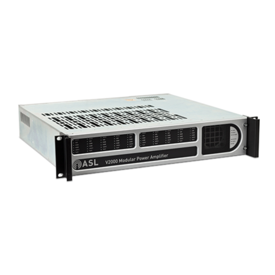
V2000
Modular Amplifier Mainframe
(LSZDC and V2000-STBY Interface Cards shown as example.)
Advertisement
Table of Contents

Related Manuals for ASL INTERCOM V2000


Summary of Contents for ASL INTERCOM V2000
- Page 1 Phone 0407442822 Emal: Sales@morrisonsav.com.au V2000 Modular Amplifier Mainframe (LSZDC and V2000-STBY Interface Cards shown as example.) (Silver front panel with silver annotation on a black background / black annotation on a silver background) User’s Manual ASL Document Ref.: U-0623-0383.docx Issue: 05 complete, approved - Date: 17/12/15...
- Page 2 V2000 User’s Manual This product must be disposed of in accordance with the WEEE directive. Copyright © 2015 Application Solutions (Safety and Security) Limited Application Solutions (Safety and Security) Limited Unit 17 Cliffe Industrial Estate Lewes - East Sussex BN8 6JL - UK...
-
Page 3: Table Of Contents
No Learn Check ..........................11 PC ..............................11 V2000 IP address configuration ......................12 V2000 Power Up ..........................12 ASL Transfer Tool – V2000 IP Configuration ..................13 PAVA System Configuration ........................14 PAVA Static Configuration ........................ 15 6.1.1 VIPEDIA-12 Static Configuration....................... 15 6.1.2... - Page 4 V2000 User’s Manual U-0623-0383.docx – Issue: 05 complete, approved – 17/12/15 Page 4 of 36...
-
Page 5: Introduction
This guide will also provide some basic information on VIPEDIA-12 Router configuration, required for full V2000 functionality. The term ‘PAVA system’ will be used when referring to the system as a whole (VIPEDIA-12 + V2000 + other related hardware). The diagram below provides an overview of the configuration and commissioning process. -
Page 6: Safety And Precautions
Objects filled with liquids should not be placed upon it. Weight Safety The V2000 mainframe with amplifier and interface cards fitted is heavy (max. 15 kg). Move and handle with care to avoid strain or impact injuries. Install amplifier modules after mounting mainframe into the equipment rack. - Page 7 Take care to avoid short-circuits of the battery supply by tools or jewellery. Do not allow tools or unconnected cables to rest on top of batteries. The V2000 may be energised after operation of a fuse or power off by the front panel MAINS and BATTERY supply switches.
- Page 8 Blanking Plate Disposal Any blanking plates removed from the V2000 as part of the installation process ideally should be recycled as metal or otherwise responsibly disposed of by following WEEE protocols.
-
Page 9: V2000 Controls And Indication
V2000 User’s Manual V2000 Controls and Indication 3.1 Front View – front panel fitted Amplifier LED indications Frame LED indications power – lights when power is in the amplifier mains – lights when mains power present at rear • •... -
Page 10: Requirements
A RS485 data connection to PC (optional, for troubleshooting) • All hardware is to be installed in the rack and ready to use. Use the V2000 Installation Guide for guidance. There are two power switches on the front of the V2000: MAINS and BATTERY. Ensure these are both switched OFF for all units. -
Page 11: Vipedia-12
4.3.4 No Learn Check The V2000 does not use the learn feature found on VIPEDIA-12. In order to prevent the no learn fault to be continuously reported the feature needs to be disabled. Refer to the VIPEDIA-12 User’s Manual for guidance. -
Page 12: V2000 Ip Address Configuration
NOTE: Fault LEDs may light during the configuration and commissioning stages. This is normal. 2. Wait for the unit to fully power up. The V2000 will be fully powered up when the amplifier Select LEDs stop flashing. This can take up to a minute, depending on the number of amplifiers fitted. -
Page 13: Asl Transfer Tool - V2000 Ip Configuration
V2000 User’s Manual 5.2 ASL Transfer Tool – V2000 IP Configuration The V2000’s IP settings are configured using the ASL Transfer Tool. The tool is launched from within the System Configuration Tool or as standalone. 1. Select the ‘Device IP’ tab - see Figure 1 a) Set the PC IP address at the top. -
Page 14: Pava System Configuration
Contains the static configuration for the whole ASL PAVA system (including V2000s), and is • unlikely to change frequently. It is saved to a file (.xml format) and uploaded to all V2000’s and VIPEDIA-12’s. • Defines which V2000 features will be available for dynamic configuration. -
Page 15: Pava Static Configuration
Right-click the V2000 in the left-hand navigation pane. b) Click ‘Add’ and then ‘Battery’. Ensure a battery added to every V2000 that uses a battery backup system. An incorrect configuration could cause damage to the V2000 hardware. 3. Configure the V2000 Frame Settings: a) Select the V2000 frame to be configured in the left- hand navigation pane. - Page 16 The amplifier will now convert to a standby. The V2000 only allows a maximum of 2000W power to be configured and saved. The Total Frame Power bar is displayed on the tool to assist with configuration. The bar will turn red and a warning icon will appear on the left if the power is over-allocated Note: If the frame is used as an external standby for another frame, the power bar will reflect this.
-
Page 17: System Static Configuration Upload
Finished transfer to ###” (### being the device(s) selected) NOTE: It is now safe to use the BATTERY power switch on all V2000’s using a battery backup system. U-0623-0383.docx – Issue: 05 complete, approved – 17/12/15 Page 17 of 36... -
Page 18: Pava Dynamic Configuration
The tool is launched from within the System Configuration Tool or as standalone. VIPEDIA-12 Audio Output Commissioning The V2000 requires VIPEDIA-12 output Limiter and output Clipper to be enabled on all V2000 connected outputs. This is to ensure VIPEDIA-12 output audio does not overload the V2000 inputs. -
Page 19: Vipedia-12 Surveillance Generator Commissioning
V2000 User’s Manual VIPEDIA-12 Surveillance Generator Commissioning The V2000 requires a continuous low level 20Hz surveillance tone from the VIPEDIA-12 outputs. This tone is used for input surveillance detection. To commission the 20Hz VIPEDIA-12 surveillance tone: a) Launch the PAVA System Configuration Tool. -
Page 20: V2000 Dynamic Commissioning
DC End of Line (DC-EOL) – Detects resistors fitted at the end of each loudspeaker spur. Impedance Line Monitoring – Monitors the impedance of the loudspeaker line. A configurable internal tone is sent from the V2000 down the speaker line to provide the voltage required for measurement. (High frequency tone only) (Feature not yet available). -
Page 21: V2000 System Surveillance Commissioning
V2000 User’s Manual V2000 System Surveillance Commissioning 1. Connect to a V2000 using the V2000 Dynamic Configuration Tool: a) Launch the tool. b) Select a frame and click ‘Connect’. c) Connection will be successful when the red connection status indicator in the top right of the tool turns to, and stays, green. - Page 22 V2000 User’s Manual The static configuration determines which dynamic features are available for commissioning. If an expected feature is not available, confirm the static configuration is correct before continuing. Static setting Dynamic feature Frame settings – Earth Leakage Detection Earth Leakage Frame settings –...
- Page 23 V2000 User’s Manual Figure 11 V2000 Dynamic Configuration Tool – Surveillance Commissioning Table 1 below gives example readings and threshold settings for input and amplifier output surveillance for reference. The readings in this table are examples using these surveillance tone settings: V2000 Low Frequency = 1.5V...
-
Page 24: Backup / Restore Dynamic Configuration
Backup / Restore Dynamic configuration After commissioning is complete for the unit it is recommended to back up the system. To backup and restore each V2000’s dynamic configuration use the Extract and Inject feature of the V2000 Dynamic Configuration Tool. -
Page 25: Audio Settings
The exception would be if an ILP01 Induction Loop panel is used on a V2000 output. Instructions for this are in section 7.3.1 – Induction Loop below. -
Page 26: Induction Loop
V2000 User’s Manual 7.3.1 Induction loop Use the following EQ settings when configuring a V2000 output for an ASL ILP01 induction loop: Band 1: • Filter = Peak, Frequency = 300Hz, Gain = -2dB, Q = 1 Band 8: •... -
Page 27: Vipedia-12 Fault Codes For V2000
• Battery high impedance FRMXX PSU POWER Indicates a fault with the PSU Fully power down the V2000, remove PCB board. the lid, and check the internal cabling. XX=Frame ID Check the rack ventilation / cooling Aux voltage out of range •... - Page 28 YY=Slot number Faulty amplifier • Check the rack ventilation, spacing Amplifier temperature • above and below V2000 unit is correct, alarm and amplifier audio load. Replace amplifier. FRMXX / AMPYY Indicates a fault with the Check the LSZDC is fitted correctly.
-
Page 29: Troubleshooting Guide
Upload: If the ‘Send Config’ operation fails: Check the IP address of the host PC. It needs to be on the same subnet as the target V2000. • Try sending the configuration to individual units, instead of to all V2000s. -
Page 30: V2000 Dynamic Configuration Tool
• ip’. Check the IP address of the host PC. It needs to be on the same subnet as the target V2000 • Confirm the windows firewall settings are correct. If in doubt re-install the tool in another location to •... -
Page 31: Firmware
• • CPLD (Factory programmed) To check the V2000 firmware versions use the V2000 Dynamic Configuration Tool. Refer to section 6.2.2 – V2000 Dynamic Configuration Tool. (Figure 19 shows an example of the dynamic tool, with the firmware versions displayed.) -
Page 32: V2000 Host And Lszdc Dsp Firmware Update
V2000 User’s Manual 10.2 V2000 Host and LSZDC DSP firmware update If instructed by ASL to update the firmware of the V2000 frame controller Host, or the LSZDC DSP, refer to ASL document: Firmware and Configuration Load Procedures (ASL document U-0641-2585) Never update firmware unless instructed by ASL U-0623-0383.docx –... -
Page 33: Pc Requirements
V2000 User’s Manual 11 PC Requirements The PC requires Windows XP or later. • Ensure the host PC has an Ethernet connection to the network containing the target PAVA units. • Alternatively, the host PC can be directly connected to either Ethernet ports on the rear of the units. -
Page 34: Maintenance
9.50 12.3 Visual Inspection A visual inspection of the V2000 and batteries (if used) should be carried out at maximum intervals of three months, as part of the system maintenance schedule. Carry out a thorough visual inspection looking for signs of corrosion on or around the unit and batteries for signs of leakage, a cracked case or top, missing protective caps etc. - Page 35 V2000 User’s Manual Notes U-0623-0383.docx – Issue: 05 complete, approved – 17/12/15 Page 35 of 36...
Need help?
Do you have a question about the V2000 and is the answer not in the manual?
Questions and answers