Table of Contents
Advertisement
Quick Links
See also:
User Manual
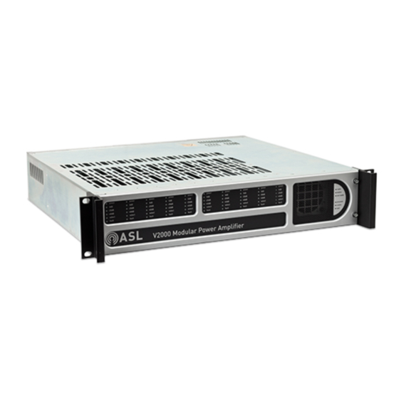
V2000
Modular Amplifier Mainframe
(LSZDC and V2000-STBY Interface Cards shown as example.)
(Silver front panel with silver annotation on a black background / black annotation on a silver background)
Installation Guide
ASL Document Ref.: U-0623-0291.docx
Issue: 04 complete, approved - Date: 10/07/15
Part Number: M0623_26
Advertisement
Table of Contents

Subscribe to Our Youtube Channel
Related Manuals for ASL INTERCOM V2000


Summary of Contents for ASL INTERCOM V2000
- Page 1 V2000 Modular Amplifier Mainframe (LSZDC and V2000-STBY Interface Cards shown as example.) (Silver front panel with silver annotation on a black background / black annotation on a silver background) Installation Guide ASL Document Ref.: U-0623-0291.docx Issue: 04 complete, approved - Date: 10/07/15...
-
Page 2: Table Of Contents
Storage and Preservation ............................35 Packing for Return ..............................36 Additional User Documentation: V2000 User’s Manual (ASL U-0623-0383) ASL System Design Guide (ASL T-0667-0185) Additional reference information is available from the ASL’s website: www.asl-control.co.uk Copyright © 2015 Application Solutions (Safety and Security) Limited... -
Page 3: Introduction
V2000 – Installation Guide Introduction This document describes how to install the V2000 Amplifier Mainframe and associated Interface Cards into a pre-wired equipment rack. The diagram below provides an overview of the installation sequence. Summary of Task Section Step(s) Page Safety and Precautions Read the safety and precautions instructions and guidelines. -
Page 4: Safety And Precautions
Objects containing liquids should not be placed upon the equipment. Weight Safety The V2000 mainframe with amplifier and interface cards fitted is heavy (max. 15 kg). Move and handle with care to avoid strain or impact injuries. Install amplifier modules after mounting mainframe into the equipment rack. - Page 5 Take care to avoid short-circuits of the battery supply by tools or jewellery. Do not allow tools or unconnected cables to rest on top of batteries. The V2000 may be energised after operation of a fuse or power off by the front panel MAINS and BATTERY supply switches.
- Page 6 Blanking Plate Disposal Any blanking plates removed from the V2000 as part of the installation process ideally should be recycled as metal or otherwise responsibly disposed of by following WEEE protocols. U-0623-0291.docx – Issue: 04 complete, approved...
-
Page 7: Preparation
A standard 19-inch rack is required for the installation. The rack should be fitted with battery backup system (if used), supporting rails for the V2000 mainframe, fan trays (if required), cooling ducts (if required), ventilation panels (if required) and wired... -
Page 8: Unpacking And Handling
Unpack the equipment in a dry area handling the equipment with care. The V2000 mainframe, interface cards and amplifier modules contain static-sensitive devices. Observe ESD precautions when handling the mainframe with the lid removed, the interface cards or amplifier modules. -
Page 9: Installation
Use the underside edges of the mainframe to lift and carry it. Do not connect cables or other wiring to the V2000 until instructed. V2000 (Blanking plates fitted to the rear panel.) - Page 10 V2000 – Installation Guide If fitted, remove the V2000 front panel by undoing the 2 x captive screws on the right-hand side of the front panel. Note that the V2000 Build Standard (BS) is the last section of the product’s barcode which is located on the mainframe front panel (behind the removable front panel);...
- Page 11 V2000 – Installation Guide Ensure all DIP switches on the mainframe controller board are in the UP position. The mainframe controller board is located on the rear left-hand corner. All switches in the UP position Set the rear-panel EARTH LIFT switch to the DOWN ( , ON) ‘grounded’...
- Page 12 V2000 – Installation Guide If used, fit one or two V2000-STBY Interface Cards to the rear panel standby interface card slots as required by your system design. If the mainframe is to be fitted with a single V2000-STBY Interface Card, the interface card should be fitted into the right-hand side standby interface card slot as illustrated below.
- Page 13 Ensure that all unused standby interface card slots are covered with a Standby Blanking Plate. Any blanking plates removed from the V2000 as part of the installation process ideally should be recycled as metal or otherwise responsibly disposed of by following WEEE protocols.
- Page 14 V2000 – Installation Guide Set the standby links on the rear side of the backplane according to the number of V2000-STBY Interface Cards fitted to the mainframe. Ensure the standby links are correctly set on the V2000 backplane. If incorrectly set, amplifiers may get damaged when a standby amplifier changes over.
- Page 15 V2000 – Installation Guide 1 x V2000-STBY Interface Card fitted: Ensure these links are NOT FITTED. If fitted, amplifiers may get damaged when the standby amplifier switches over. LINKS FITTED LINKS NOT FITTED ‘Handbag’ style 2-pin shortening link, 5.08 mm pitch...
- Page 16 LINKS NOT FITTED handling electrostatic sensitive devices. Cover all unused LSZDC Interface Card slots with a V2000 Surveillance Blanking Plate as specified in your system design. The example below shows a blanking plate covering slots 2, 4, 6, 8 and 10.
- Page 17 V2000 – Installation Guide Fit the LSZDC Interface Cards to the rear panel surveillance interface card slots as required by your system design. The illustrations below show a LSZDC Interface Card being fitted into slot 1. Insert the LSZDC Interface Card so that its rear connector mates the matching connector on the backplane by seating the tab at the bottom of the interface card in the appropriate notch on the midline rear support.
- Page 18 V2000 – Installation Guide Ensure that the interface card is fully pushed, and then secure it using 2 x screws. Ensure all securing screws are fully tightened to bond the interface card to the amplifier mainframe chassis. It is important to make sure the screws are fully tightened to prevent dangerous voltages being present on the panel.
- Page 19 Comms Fault Ensure that the mains and battery supplies to the mainframe are isolated. Mains supply isolator: example using ASL MDIST-V2000 Isolate the AC mains supply to the unit by switching off the rack mains isolator. In racks fitted with ASL MDIST-...
- Page 20 Fit the mainframe into a 19-inch standard equipment rack on supporting rails, and secure the mainframe in position using fixing screws and washers. The V2000 mainframe with amplifier and interface cards fitted is heavy (max. 15 kg). Move and handle with care to avoid strain or impact injuries.
- Page 21 V2000 – Installation Guide Install the amplifier modules as required by your system design. Fully open the ejector lever of the amplifier module. Position the amplifier module in the slot through the front of the mainframe. Align the sides of the module with the card guides on top and bottom of the mainframe to locate it correctly.
- Page 22 V2000 – Installation Guide Carefully slide the amplifier module into the slot until the ejector lever meets the card guide at the bottom. Pivot the ejector lever up just so that the ejector lever hook fits into the gap Mainframe between the bottom card guide and the mainframe hem.
- Page 23 The Ethernet cables should not be connected to the V2000 until system commissioning as all V2000 units are supplied with same IP settings (factory default).
- Page 24 V2000 – Installation Guide Connect the AC mains power supply cable to the rear panel mains connector. If battery power supply is used, connect the battery power cable from the battery supply circuit breaker to the rear panel connector BATTERY IN/OUT.
- Page 25 Once the front panel is fitted, the power ON/OFF switches will not be accessible. Fit the V2000 front panel by sliding its left end under the left handle, and fixing its right end using the two captive screws.
-
Page 26: Connections
V2000 – Installation Guide Connections V2000 rear panel (LSZDC and V2000-STBY Interface Cards shown as example) SLOT 10 SLOT 1 ④ ⑤ ⑦ ⑥ ⑧ ① ② ③ ⑨ ⑩ V2000 Mainframe Connectors ① AC Mains Supply IEC 60445 – Conductor and Terminal Marking... - Page 27 V2000 – Installation Guide ③ BATTERY IN/OUT: Battery Supply Input and Charger Output Signal Description Battery positive input/output (21 - 28 V). External fusing of up to 80 A is required. Battery negative input/output Cabling 1 x 1-core red and 1 x 1-core black...
- Page 28 V2000 – Installation Guide ⑤ ETH1 and ETH2: 100BASE-T Ethernet Ports CAT5 Cable Signal Description (EIA 568-B) TRANSMIT+ white/orange 100BASE-T Ethernet Transmitted Data orange TRANSMIT- Same as above ETH 1 white/green RECEIVE+ 100BASE-T Ethernet Received Data blue – Not used white/blue –...
- Page 29 V2000 – Installation Guide LSZDC Line Surveillance Interface Connectors ⑦ LINE OUT: Audio Output Signal Description 100 V line audio output to speaker circuit A (+ve) As above, but –ve 100 V line audio output to speaker circuit B (+ve) As above, but –ve...
- Page 30 V2000 – Installation Guide V2000-STBY Standby Interface Card Connectors ⑨ STANDBY 100V IN: Audio from Standby Amplifier Signal Description 100 V line audio from standby amplifier (+ve) As above, but -ve Two sets of connections are provided for ‘daisy-chain’ wiring from amplifier to amplifier.
-
Page 31: Technical Specification
Dimensions (H x W x D) ........86 mm x 436 mm x 425 mm (excluding handles) / 2U height 19-inch rack mounting Weight ....7.7 kg (V2000 frame only) / 15 kg (max, frame fitted with 10 x D500/D150 and 10 x LSZDC) Colour ............................silver front panel with silver annotation on a black background / black annotation on a silver background If rack internal ambient temperature can exceed 40°C then additional forced cooling is required. - Page 32 V2000 – Installation Guide D150 Amplifier Module Type ....................... transformerless class D amplifiers Output Power ................5 W to 150 W (down to 21 V battery supply) Output Voltage and Input sensitivity ... 100 / 70 / 50 V RMS into 150 W load for 0 dBu 1 kHz input signal Regulation .........................
- Page 33 V2000 – Installation Guide LSZDC Line Surveillance Interface Card Current Consumption (average, without changeover, 24 V supply) Normal ..............................7.5 mA Loop Return Mode ..........................39 mA Current Consumption (average, with relays operating, 24 V supply) ....39 mA with one isolation relay...
-
Page 34: Mechanical Dimensions
V2000 – Installation Guide Mechanical Dimensions (Interface cards shown as example) 436 mm THIRD ANGLE PROJECTION approx. 487 mm (including handles) U-0623-0291.docx – Issue: 04 complete, approved Page 34 of 40... -
Page 35: Storage And Preservation
V2000 – Installation Guide Storage and Preservation This product should be packed for storage in the original packing as described in the Section ‘10 Packing for Return’ (page 36) and stored in the following environmental conditions: • Away from harsh environmental conditions, such as areas that are subject to corrosive atmosphere, excessive moisture or may allow water or other liquids to come into contact with the unit or its external connections. -
Page 36: Packing For Return
V2000 – Installation Guide Packing for Return The V2000 mainframe, interface cards and amplifier modules contain static-sensitive devices. Observe ESD precautions when handling the mainframe with the lid removed, the interface cards or amplifier modules. If a product is being returned for servicing, try to use the containers and materials of the original packaging. - Page 37 V2000 – Installation Guide Notes U-0623-0291.docx – Issue: 04 complete, approved Page 37 of 40...
- Page 38 V2000 – Installation Guide Notes U-0623-0291.docx – Issue: 04 complete, approved Page 38 of 40...
- Page 39 V2000 – Installation Guide Notes U-0623-0291.docx – Issue: 04 complete, approved Page 39 of 40...
- Page 40 Service and Warranty Name and Address of Authorised Distributor: This product carries a full warranty. For full details of warranty and service agreements, please contact the Authorised Distributor who supplied the product to you. Exclusions The warranty does NOT cover: Customer misuse, including incorrect installation.
Need help?
Do you have a question about the V2000 and is the answer not in the manual?
Questions and answers