
Related Manuals for ASL INTERCOM V400


Summary of Contents for ASL INTERCOM V400
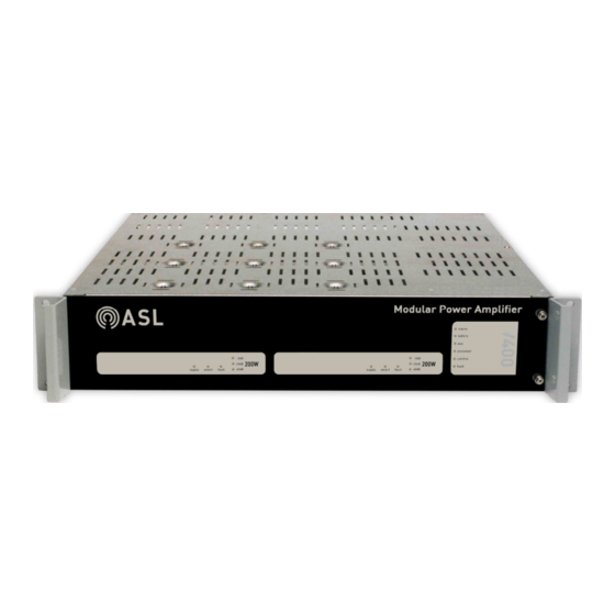
- Page 1 V400 Amplifier Mainframe (V400 fitted with 2 x M200 Amplifier Modules for illustrative purposes only.) Installation Guide ASL Document Ref.: U-0398-0607.doc Issue: 03 complete, approved - Date: 25/10/11 Part Number: M0398_63...
- Page 2 V400 – Installation Guide This equipment is designed and manufactured to conform to the following EC standards: EMC: EN55103-1/E1:1996, EN55103-2/E5:1996, EN50121-4:2006, ENV50204:1995, EN61000-4-13:2002 Safety: EN60065:2002 (pollution degree 2) Voice Alarm: When installed in a Voice Alarm system designed in accordance with the ASL EN 54-16 &...
- Page 3 230 V mains supply Inrush Current (worst case)............................24.2 A Maximum AC Power Consumption.......745 VA (V400 fully configured and all amplifier modules delivering 100 V 1 kHz sinewave into rated resistive loads) DC Supply Voltage............21 to 28 V (from nominal 24 V lead acid battery pack) / T25A fuse Quiescent DC Current (no amplifiers, @ 24 V supply) ....................
- Page 4 0 dB supply select fault −20 dB −40 dB processor comms fault (V400 fitted with two M200 200 W Amplifier Modules as example.) DETAIL WITHOUT FRONT PANEL: BATTERY ISOLATION SWITCH MAINFRAME ADDRESS MAINS ISOLATION SWITCHES SWITCH U-0398-0607.doc – Issue: 03 complete, approved...
- Page 5 V400 – Installation Guide Amplifier Module Indicators Indicator Type Indication supply Green LED Indicates that power is present at the amplifier. Illuminates to indicate that the amplifier is selected for commissioning or audio monitoring by the system. select Green LED In the case of a standby amplifier it illuminates to indicate that the standby is in use.
- Page 6 V400 – Installation Guide Equipment and Tool Requirements • The V400 Amplifier Mainframe. • M100, M200, or M400 amplifier modules as specified in your system design documentation. • A mainframe front panel to suit the amplifier configuration. • Cabling as specified in “External Cabling Requirements” (page 7) to suit your system design.
- Page 7 V400 – Installation Guide External Cabling Requirements Signals Cable Description Termination Suggested Type 1 x 3-core mains Suitably rated standard standard cable 1) 6) AC mains supply IEC 60320 socket mains cable Current rating: 6.3 A 1 x 1-core red...
- Page 8 Failure to follow these instructions and guidelines may cause personal injury and/or damage to the equipment. If fitted, then remove the V400 front panel by undoing the two captive M3 Pozidriv screws on the right side of the front panel.
- Page 9 V400 – Installation Guide If a M400 Amplifier Module is being inserted, and connected to an ASL AEL (Active End of Line Device), the link setting on the M400 Amplifier Module needs to be adjusted as shown; see Figure 3.
- Page 10 V400 – Installation Guide Figure 4 Installing the Amplifier Modules into the V400 M200 MODULE SIDE PANELS MUST LOCATE IN MAINFRAME SLIDES (1 x M200 shown as example.) M200 STANDARD CONFIGURATIONS: 4 x M100 CONFIGURATION 1 x 200 W + 2 x 100 W CONFIGURATION...
- Page 11 V400 – Installation Guide Figure 5 Fitting the transit screws FIT THE RIGHT HAND M3 TRANSIT POZIDRIV SCREW ON THE RIGHT-MOST AMPLIFIER MODULE ONLY AS SHOWN BELOW. FIT THE M3 TRANSIT POZIDRIV SCREWS TO THE LEFT HAND SIDE OF ALL AMPLIFIER MODULES AS SHOWN ABOVE.
- Page 12 V400 – Installation Guide Set the rear-panel EARTH LIFT switch to the DOWN ( , ON) ‘grounded’ position; see Figure 7. Set the EARTH LIFT switch to the UP ( , OFF) position to remove the mains earth from the signal circuit if a +ve ground battery system is used, or it is necessary to avoid a ground loop problem.
- Page 13 V400 – Installation Guide Figure 8 DIP Switch Selection DIP switch position on the rear of V400 DIP switch in the “OFF” position DIP switch in the “ON” position SW No. Switch Name Function when ON Function when OFF Amplifier mainframe is automatically...
- Page 14 Loop Return LK10 fitted Insert the required interface cards into the rear of the V400 amplifier mainframe, ensuring it is in the correct position to mate with its amplifier module and push it home; see Figure 10. All empty slots must be covered with blanking panels (ASL P/N: RBLANK-V400).
- Page 15 OVERRIDE LINK SCREEN (Rear view of V400 mainframe fitted with LSDDC Interface Cards as example.) Connect the field wiring to the installed Interface Cards. Please refer to Section “2 Connection” (page 18) for pinout details. If AEL (Active End of Line Device) is used, then install the AEL unit referring to the AEL Installation Guide.
- Page 16 V400 – Installation Guide If DC power supply is used, then connect the DC supply cable; see Figure 11. External 24 V DC batteries unit can deliver very high currents that could cause fire or burns. Take care to avoid short circuits of the battery supply by tools or jewellery.
- Page 17 V400 – Installation Guide Fit the mainframe front panel by sliding its left end under the left V400 handle, and fixing its right end using the two captive M3 Pozidriv screws; see Figure 12. Figure 12 Fixing the mainframe front panel...
- Page 18 V400 – Installation Guide Connection Figure 13 Rear of V400 with SSINT and LSDDC Interface Cards (Example) SSINT LSDDC LSDDC LSDDC AC MAINS INLET MAINS SUPPLY: IEC 60320 STANDARD PLUG (MALE) Signal Description Live Earth Neutral L E N Mains supply: European standard 230 V AC ±10% / 50-60Hz Fuse: T6.3A L 250 V...
- Page 19 V400 – Installation Guide AUDIO CAN/STATUS PORTS AUDIO CAN /STATUS: DUAL 9-WAY D CONNECTOR (FEMALE) Pin No Signal Description Not Connected Not Connected CAN_L Controller Area Network (Low) AUDIO MON CAN_L 0 V Reference AUDIO MON- Audio Monitor Bus (–10 dBu nominal) AUDIO MON+ Audio Monitor Bus (–10 dBu nominal)
- Page 20 V400 – Installation Guide LSDDC CONNECTIONS AUDIO INPUT: 3-WAY PLUGGABLE WAGO CAGE CLAMP (MALE) Signal Description Screen Cable screen INPUT “+” Balanced audio input at 0 dBu SCREEN “-” Balanced audio input at 0 dBu LOW LEVEL STANDBY AND OVERRIDE LINK: DUAL RJ45...
- Page 21 V400 – Installation Guide NSINT CONNECTIONS AUDIO INPUT: 3-PIN XLR (FEMALE) Pin No Signal Description Signal common Cable screen (see Note below) Audio I/P + Balanced audio input at 0 dBu Audio I/P - Balanced audio input at 0 dBu For best EMC performance, always connect cable screen to the back shell of the connector.
- Page 22 V400 – Installation Guide Safety and Precautions Electrical Safety Environmental Always ensure adequate ventilation is provided for the This product contains wiring that is equipment by fitting 1U ventilation panels above and energised to 230 V AC mains and below the equipment and do not obstruct ventilation 100 V RMS audio signals at up to 20 kHz.
- Page 23 V400 – Installation Guide Ground Loops Packing for Return for Repair It is possible to form a ground loop (earth loop or hum All electronics assemblies must be loop) when connecting pieces of audio equipment using properly packed in ESD protective...
- Page 24 Service and Warranty Name and Address of Authorised Distributor: This product carries a full warranty. For full details of warranty and service agreements, please contact the Authorised Distributor who supplied the product to you. Exclusions The warranty does NOT cover: Customer misuse, including incorrect installation.
Need help?
Do you have a question about the V400 and is the answer not in the manual?
Questions and answers