Table of Contents
Advertisement
Quick Links
www.zeeltronic.com
info@zeeltronic.com
updated 03.01.2009
program version: 000.021008
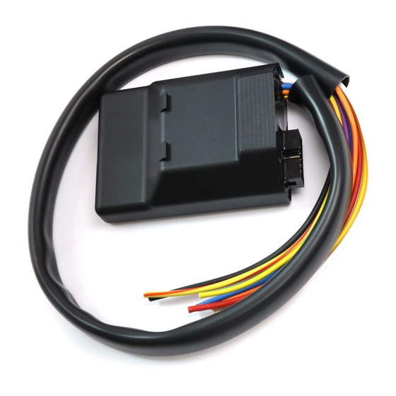
PROGRAMMABLE CDI IGNITION AND PV CONTROLLER
TECHNICAL DATA
Limit values:
- minimum revs
- maximum revs
- minimum supply voltage
- maximum supply voltage
- max. supply voltage for 1 minute
- current draw
- maximum continuous current for shift light output
- peak current for shift light output
Circuit is protected against reverse supply voltage (wrong connection).
Features:
- CDI charged from hi voltage charging coils (generator)
- store and load function for 2 ignition maps
- one input for magnetic pickup
- external switch for changing ignition map while riding
- shift light output
- quick shift (shift kill)
- tachometer output
- advance/retard whole ignition curve
- three stage rev limit (retard timing, reduced spark, spark off)
- signal delay compensation
- timing calculation for every 1 RPM change (1000, 1002, .. , 9805, 9806, ...)
- easy and fast programming on the field, via hand held programmer
- programming while machine running - you can immediately see effects
- monitoring of rev's, ignition advance,... via LCD(hand held programmer)
- fast processing for high accuracy - delays from 1us
USER MANUAL
PCDI-10
- 1 -
200 RPM
20000 RPM
8 Volts
16 Volts
35 Volts
25 mAmp
1 Amp
5 Amp
Advertisement
Table of Contents

Related Manuals for zeeltronic PCDI-10


Summary of Contents for zeeltronic PCDI-10
- Page 1 03.01.2009 program version: 000.021008 USER MANUAL PCDI-10 PROGRAMMABLE CDI IGNITION AND PV CONTROLLER TECHNICAL DATA Limit values: - minimum revs 200 RPM - maximum revs 20000 RPM - minimum supply voltage 8 Volts - maximum supply voltage 16 Volts - max.
- Page 2 HOW TO ENTER MENU PCDI must be connected to power supply. Connect programmer to PCDI and wait few seconds for activation of programmer and then press enter. With pressing + or - you can move through menu and select with pressing enter . Exit menu with selecting Exit.
- Page 3 Important! To avoid wrong processing, don't make unreasonable curve course. Every time you make any changes to ignition curve, it is automatically saved to #0 position. Then you can save it to any other position number from #1 to #2. Curve Example with six curve points: 5.1.
- Page 4 Set SHIFT LIGHT Enter menu and move to Shift Light with pressing + or - and then press enter . Now you can change rev point with pressing + or - (in 100 rpm steps) and then press enter . Set SHIFT KILL TIME Enter menu and move to Shift Kill Time with pressing + or - and then press enter .
- Page 5 MECHANICAL SETTINGS (Static Angle) Static Angle is ignition advance angle, set with stator (generator). Measure this angle with dial gauge. This measured Static Angle is your maximum advance angle you can set with PCDI. Example: Measured Static Angle = 39.2deg (this angle you must enter in PCDI) Calculating mm to deg or vice versa: MONITORING...
Need help?
Do you have a question about the PCDI-10 and is the answer not in the manual?
Questions and answers