Table of Contents
Advertisement
Quick Links
www.zeeltronic.com
info@zeeltronic.com
updated 04.04.2011
program version: 20.310311
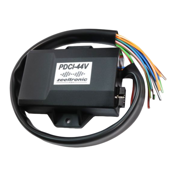
PDCI-44V PROGRAMMABLE CDI IGNITION AND PV CONTROLLER
Limit values:
- minimum revs
- maximum revs
- minimum supply voltage
- maximum supply voltage
- normal operating voltage
- stand-by current draw
- current draw at 1300 RPM
- current draw at 12000 RPM
- maximum continuous current for shift light and power jet output
- peak current for shift light and power jet output
- constant spark energy from idle to 14000 RPM
Circuit is protected against reverse supply voltage (wrong connection).
Features:
- fast power-up
- full power starting spark energy already at 7Volts power supply
- two isolated input (pickup)
- four independent ignition coil outputs
- individual advance/retard of each ignition coil output
- store and load function for two ignition maps
- external switch for changing ignition map while riding
- TPS input (Throttle Position Sensor)
- shift light output
- 2 power jet outputs
- duty cycle solenoid output (for regulating A/F ratio on some carburettors)
- quick shift (shift kill)
- soft rev limit (three stage rev limit)
- reduced spark at high revs with closed throttle (TCT mode)
- tachometer output
- easy and fast programming on the field, via hand held programmer
- programming while machine running - you can immediately see effects
- each curve can be set in 4 to 12 curve points
- 3D interpolated ignition map, if TPS selected
- signal delay compensation
- instant monitoring of rev's and angle, via LCD(hand held programmer)
USER MANUAL
- 1 -
200 RPM
20000 RPM
7 Volts
18 Volts
12 ÷ 14,5 Volts
< 0.09 Amp
< 0.5 Amp
~ 3 Amp
1 Amp
5 Amp
>35mJ
Advertisement
Table of Contents

Related Manuals for zeeltronic PDCI-44V


Summary of Contents for zeeltronic PDCI-44V
- Page 1 04.04.2011 program version: 20.310311 USER MANUAL PDCI-44V PROGRAMMABLE CDI IGNITION AND PV CONTROLLER Limit values: - minimum revs 200 RPM - maximum revs 20000 RPM - minimum supply voltage 7 Volts - maximum supply voltage 18 Volts - normal operating voltage 12 ÷...
-
Page 2: Menu Organisation
- programmable power valve actuation - store and load function for 5 PV curves - external switch for changing PV curve while riding - programmable PV deviation - programmable max close and max open positions - self PV test on power-up - PV error detecting (position sensor failure, servo motor failure) - fast processing for high accuracy - delays from 1us - timing calculation for every 1 RPM change (1000, 1002, .. - Page 3 - enable, or disable TPS TPS close [0%] - calibrating TPS close position TPS open [100%] - calibrating TPS open position TCT mode - reduced spark at high revs with closed throttle Ign. Map SW - activating/deactivating external switch for selecting ignition map Pulses Per Rev - number pulses per revolution from pickup Stop SW mode...
- Page 4 Important! To avoid wrong processing, don't make unreasonable curve course. Every time you make any changes to ignition curve, it is automatically saved to number #0. Later you can save it to any other number #1 or #2. Curve Example with six curve points: 5.1.
- Page 5 Important! To avoid wrong processing, don't make unreasonable curve course. Every time you make any changes to ignition curve, it is automatically saved to number #0. Later you can save it to any other number #1 or #2. Ignition Map Example: 5.2.
- Page 6 ADVANCE 1 With this setting is possible to advance, or retard ignition map on ignition coil output 1. When setting is positive, then ignition map is advanced and when setting is negative than, ignition map is retarded. Ignition map is unchanged, with setting 0.0deg. Enter menu and move to Advance, with pressing + or - and then press enter .
- Page 7 QUICK SHIFT Enter Set Ign. menu and move to Quick Shift with pressing + or - and then press enter ..you entered submenu for quick shift settings. Submenu organisation: Shift Kill Time - basic kill time Smart Shift - activating/deactivating automatic kill time for different revs Exit - exit submenu 12.1.
- Page 8 Change Compensation: Enter menu and move to Compensation with pressing + or - and then press enter . Now you can change compensation delay with pressing + or - and then press enter . POWER JET 1 Enter Set Ign. menu and move to Power Jet 1 with pressing + or - and then press enter ..you entered submenu for setting Power Jet 1 parameters.
- Page 9 16.3. POWER JET 1 ON (if TPS enabled) Enter Set Ign. menu and move to Power Jet 1 ON with pressing + or - and then press enter . Now you can change TPS position with pressing + or - (in 1%TPS steps) and then press enter .
- Page 10 17.3. DUTY SOLENOID (if selected in Output Type menu) Three duty cycle curves for different throttle positions can be programmed. Each curve can be programmed in 8 rev points. Enter Solenoid Output menu and move to Duty Solenoid with pressing + or - and then press enter .
-
Page 11: Ignition Test
TCT mode Throttle Close spark Termination mode, reduces number of sparks (spark is active every third revolution) above 8000rpm, when throttle is closed. TCT mode ensure better engine cooling. Enter Set Ign. menu and move to TCT mode with pressing + or - and then press enter . Now you can enable or disable TCT mode with pressing + or - and then press enter . - Page 12 SAVE PV CURVE Enter Set PV menu and move to Save PV Curve with pressing + or - and then press enter. Now you can select number to save your PV curve, with pressing + or - and then press enter . Set PV Curve Enter Set PV menu and move to Set PV Curve with pressing + or - and then press enter .
-
Page 13: Close Position
CLOSE POSITION Max close position must be calibrated after installation. Max close position is when curve is set to 0%. Close position can be moved to any desired position. Enter Set PV menu and move to Close Position with pressing + or - and then press enter . Now you can set close position with pressing + or - and then press enter . -
Page 14: Error Reports
MECHANICAL SETTINGS (Static Angle) Static Angle is ignition advance angle, set with stator (generator). Measure this angle with dial gauge. This measured Static Angle is your maximum advance angle you can set with PDCI. Calculating mm to deg or vice versa: MONITORING Connect programmer to PDCI and wait few seconds for activation of programmer.
Need help?
Do you have a question about the PDCI-44V and is the answer not in the manual?
Questions and answers