Advertisement
Quick Links
www.zeeltronic.com
info@zeeltronic.com
updated 02.03.2018
program version: 31.180301
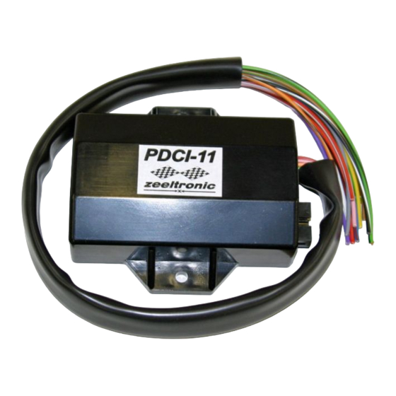
PDCI-11 PROGRAMMABLE CDI IGNITION
TECHNICAL DATA
Limit values:
- minimum revs
- maximum revs
- minimum supply voltage
- recommended power supply voltage
- maximum supply voltage
- stand-by current draw
- current draw at 1300 RPM
- current draw at 12000 RPM
- maximum continuous current for shift light and power jet output
- peak current for shift light and power jet output
- constant spark energy from idle to 20000 RPM
Features:
- fast power-up (also starts only with condenser)
- full power starting spark energy already at 8Volts power supply
- one isolated input for magnetic pickup
- store and load function for two ignition maps
- external switch for changing ignition map while riding
- TPS input (Throttle Position Sensor)
- shift light output
- power jet output
- duty cycle solenoid output (for regulating A/F ratio on some carburettors)
- quick shift (shift kill)
- soft rev limit (three stage rev limit)
- reduced spark at high revs with closed throttle (TCT mode)
- tachometer output
- easy and fast programming on the field, via hand held programmer
- programming with PC
- programming while machine running
- 3D interpolated ignition map, if TPS used
- signal delay compensation
- instant monitoring of rev's and angle, via LCD(hand held programmer)
- fast processing for high accuracy - delays from 1us
USER MANUAL
1
200 RPM
20000 RPM
7 Volts
12÷15 Volts
17 Volts
< 0.05 Amp
< 0.3 Amp
< 1 Amp
1 Amp
5 Amp
>70mJ
Advertisement

Subscribe to Our Youtube Channel
Related Manuals for zeeltronic PDCI-11


Summary of Contents for zeeltronic PDCI-11
- Page 1 02.03.2018 program version: 31.180301 USER MANUAL PDCI-11 PROGRAMMABLE CDI IGNITION TECHNICAL DATA Limit values: - minimum revs 200 RPM - maximum revs 20000 RPM - minimum supply voltage 7 Volts - recommended power supply voltage 12÷15 Volts...
-
Page 2: Menu Organisation
Very important! Resistor spark plugs must be used, because they produce less electromagnetic disturbances. Very important! PDCI is protected against static discharge, but too high static charge can damage PDCI. Be careful when using programmer on the dyno, because static charge can build up on the bike and static discharge can damage PDCI unit, or programmer. - Page 3 LOAD IGN. MAP Move to Load Ign. Map with pressing + , or - and then press enter . Now you can select number of saved ignition map, with pressing + , or - and then press enter. SAVE IGN. MAP Move to Save Ign.
- Page 4 5.1. SET IGNITION MAP (if TPS enabled) Three ignition curves must be programmed for different TPS positions. PDCI does not only switch between ignition curves, but also interpolate 3D map for all TPS positions above 33%. Move to Set Ignition Map with pressing + , or - and then press enter..you entered submenu for selecting ignition curve.
- Page 5 ADVANCE With this setting is possible to advance, or retard whole ignition map on both ignition coil outputs. When setting is positive, then ignition map is advanced and when setting is negative, than ignition map is retarded. Ignition map is unchanged, with setting 0.0deg. Move to Advance, with pressing + , or - and then press enter .
- Page 6 10.2. SMART SHIFT Smart shift function automatically adjusts kill time for different revs. Shift kill time must be always set, as basic kill time. Enter Quich Shift menu and move to Smart Shift with pressing + , or - and then press enter. Now you can enable, or disable function with pressing + , or - and then press enter .
- Page 7 Example: Power jet 1 ON (RPM) = 8000rpm Power jet 1 OFF (RPM) = 10000rpm Power jet 1 ON (TPS) = 70%TPS power jet 1 OFF (TPS) = 90%TPS Power jet is switched on when revs are between 8000-10000rpm and throttle position is between 70-90%, otherwise power jet is switched off.
- Page 8 15.1. OUTPUT TYPE Solenoid output function can be configured as Power Jet 2, or Duty Solenoid. Duty solenoid is used for adjusting A/F ratio on some carburettors. Enter Solenoid Output. menu and move to Output type with pressing + , or - and then press enter .
- Page 9 Leave throttle at close position and confirm calibrating with pressing enter , or exit calibration with pressing - . Displayed number should be between 0 and 500. Set TPS open [100%] (if TPS enabled) For correct operation, TPS open position must be calibrated! Move to TPS open [100%] with pressing + , or - and then press enter.
- Page 10 MECHANICAL SETTINGS (Static Angle) Static Angle is ignition advance angle, set with stator (generator). Measure this angle with dial gauge. This measured Static Angle is your maximum advance angle you can set with PDCI. Calculating mm to deg or vice versa: MONITORING Connect programmer to PDCI and wait few seconds for activation of programmer.
Need help?
Do you have a question about the PDCI-11 and is the answer not in the manual?
Questions and answers