Advertisement
Quick Links
www.zeeltronic.com
info@zeeltronic.com
updated 07.08.2019
program version: 40.180119
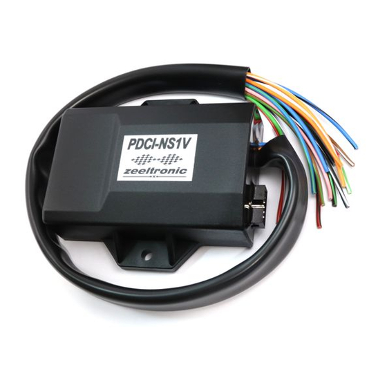
PDCI-NS1V PROGRAMMABLE CDI IGNITION AND PV CONTROLLER
PDCI-NS1V is 2 channel DC-CDI and exhaust valve controller, specially designed for
Honda RS250 and NSR250. It is programmable with handheld programmer, or PC.
Limit values:
- minimum revs
- maximum revs
- minimum supply voltage
- recommended power supply voltage
- maximum supply voltage
- stand-by current draw
- current draw at 1300 RPM
- current draw at 12000 RPM
- maximum continuous current for shift light and power jet output
- peak current for shift light and power jet output
- constant spark energy from idle to 13000 RPM
Important!
Circuit is fully protected against reverse polarity from firmware 31.170203.
Features:
- fast power-up (also starts only with condenser)
- full power starting spark energy already at 7Volts power supply
- two isolated input (pickup)
- two independent ignition coil outputs
- individual advance/retard of each output
- store and load function for two ignition maps
- external switch for changing ignition map while riding
- TPS input (Throttle Position Sensor)
- shift light output
- 2 power jet outputs(duty cycle solenoid output)
- quick shift (shift kill)
- soft rev limit (three stage rev limit)
- reduced spark at high revs with closed throttle (TCT mode)
- tachometer output
- easy and fast programming on the field, via hand held programmer
- programming while machine running - you can immediately see effects
USER MANUAL
- 1 -
200 RPM
20000 RPM
7 Volts
12÷15 Volts
17 Volts
< 0.09 Amp
< 0.3 Amp
< 1.7 Amp
1 Amp
5 Amp
>50mJ
Advertisement

Subscribe to Our Youtube Channel
Related Manuals for zeeltronic PDCI-NS1V


Summary of Contents for zeeltronic PDCI-NS1V
- Page 1 40.180119 USER MANUAL PDCI-NS1V PROGRAMMABLE CDI IGNITION AND PV CONTROLLER PDCI-NS1V is 2 channel DC-CDI and exhaust valve controller, specially designed for Honda RS250 and NSR250. It is programmable with handheld programmer, or PC. Limit values: - minimum revs...
-
Page 2: Menu Organization
- each curve can be set in 4 to 15 curve points - 3D interpolated ignition map, if TPS selected - signal delay compensation - instant monitoring of rev's and angle, via LCD(hand held programmer) - programmable power valve actuation - store and load function for 8 PV curves - external switch for changing PV curve while riding - programmable PV deviation... - Page 3 Rev Limit - rev limit Static Angle - static angle (pickup position) Compensation - signal delay compensation (from pickup to spark plug) Power Jet s - set power jets - enable, or disable TPS TPS close [0%] - calibrating TPS close position TPS open [100%] - calibrating TPS open position TCT mode - reduced spark at high revs with closed throttle...
- Page 4 SET IGNITION MAP (if TPS disabled) Enter Set Ign. menu and move to Set Ign. Map with pressing '+', or and press 'ENTER' to confirm. You entered submenu for setting ignition map. Submenu organisation: Nr. of Points - number of ignition curve points (from 4 to 15) - first ignition curve point - second ignition curve point Exit...
- Page 5 Submenu organisation: 3D Ignition Map - enable/disable 3D ignition map Nr. of Points - number of ignition curve points (from 4 to 15) Curve 0-33% - ignition curve from 0 to 33% TPS Curve 66% - ignition curve for 66% TPS Curve 100% - ignition curve for 100% TPS Exit...
- Page 6 ADVANCE With Advance setting is possible to advance, or retard whole ignition map on both ignition outputs. When setting is positive then ignition map is advanced and when setting is negative then ignition map is retarded. With Advance 0.0deg, ignition map is unchanged.
- Page 7 QUICK SHIFT Enter Set Ign. menu and move to Quick Shift with pressing '+', or and press 'ENTER' to confirm..you entered submenu Quick Shift. Submenu organisation: Shift Kill Time - basic kill time (at 12000rpm) Smart Shift - activating/deactivating automatic kill time for different revs Exit - exit submenu 10.1.
-
Page 8: Trigger Point
How to measure static angle? The most accurate procedure is with dial gauge. Apply to single and multiple cylinder engines. Necessary tools: - stroboscope light - dial gauge Follow the procedure: measure approximate static angle, just to have starting point...look at drawing below. Anticlockwise rotation: static angle TRIGGER POINT... - Page 9 Example: α =16deg (ignition advance) L=110mm (conrod length) R=54/2=27mm (engine stroke divided by 2) T=1,3mm (calculated ignition advance in mm) Equation for calculating from degrees to millimetres: α ignition advance degrees ignition advance engine stroke divided conrod length α α ⋅...
- Page 10 POWER JETS Enter Set Ign. menu and move to Power Jets with pressing '+', or and press 'ENTER' to confirm..you entered submenu Power Jets. Submenu organisation: Invert Polarity - invert power jet operation (invert open/close) set Power Jet 1 - activating/deactivating soft rev limit set Power Jet 2 - activating/deactivating soft rev limit...
- Page 11 Enter Set Ign. menu and move to TPS with pressing '+', or and press 'ENTER' confirm. Enable/disable TPS with pressing '+', or and press 'ENTER' to confirm. Set TPS close [0%] (if TPS enabled) TPS close position must be calibrated to ensure correct TPS operation! Enter Set Ign.
- Page 12 Trigger Mode Select trigger mode for specific engine. Trigger Mode '1' is for RS250 NF5 and NSR250 MC21 Trigger Mode '2' is for RS250 NX5 Enter Set Ign. menu and move to Trigger Mode with pressing '+', or and press 'ENTER' to confirm.
- Page 13 Save PV Curve Enter Set Ign. menu and move to Save PV Curve with pressing '+', or and press 'ENTER'. Select number to which you want to save your ignition curve, with pressing '+', or press 'ENTER' to confirm. Set PV Curve Enter Set PV menu and move to Set PV Curve with pressing '+', or and press 'ENTER'.
- Page 14 Deviation Enter Set PV menu and move to Deviation with pressing '+', or and press 'ENTER' confirm. Change deviation from 2% to 20% with pressing '+', or (in 1% steps) and then 'ENTER' to confirm. Deviation means how accurate valve move to calculated position. If deviation is too low then servo motor won't be stabile...it will always search for calculated position in small movements.
-
Page 15: Error Reports
PV CURVE SW Enabling, or disabling PV curve switch for changing PV curves while riding. Enter Set PV menu and move to PV Curve SW with pressing '+', or and press 'ENTER' to confirm. Enable, or disable PV Curve switch with pressing '+', or and press 'ENTER' confirm.
Need help?
Do you have a question about the PDCI-NS1V and is the answer not in the manual?
Questions and answers