Table of Contents
Advertisement
Quick Links
www.zeeltronic.com
info@zeeltronic.com
updated 18.01.2019
application version: 00.181220
PROGRAMMING MANUAL
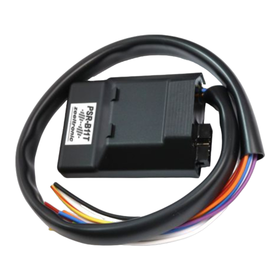
ZeelProg PSR-B11T
Supported control units: PSR-B11T
ZeelProg is PC application for programming ZEELTRONIC engine control units.
For programming special PC-USB programmer is needed.
ZeelProg automatically detects PC-USB programmer connection and enables all functions
(without PC-USB programmer, ZeelProg application is locked).
ZeelProg automatically detects type of engine control unit connected to PC-USB
programmer.
1
Advertisement
Table of Contents

Subscribe to Our Youtube Channel
Summary of Contents for zeeltronic ZeelProg PSR-B11T
- Page 1 PROGRAMMING MANUAL ZeelProg PSR-B11T Supported control units: PSR-B11T ZeelProg is PC application for programming ZEELTRONIC engine control units. For programming special PC-USB programmer is needed. ZeelProg automatically detects PC-USB programmer connection and enables all functions (without PC-USB programmer, ZeelProg application is locked).
-
Page 2: Table Of Contents
CONTENT ZeelProg SOFTWARE INSTALLATION GUIDE ZeelProg USER INTERFACE Auto detection Menu structure Ignition Parameters Misc Parameters PROGRAMMING AND SETTING NEW PARAMETERS Changing control unit parameters Make new *.zee file without connecting control unit Set TPS close position Set TPS open position MONITOR FUNCTION MEASURING STATIC ANGLE Explanation of trigger signal from pickup... -
Page 3: Zeelprog Software Installation Guide
ZeelProg SOFTWARE INSTALLATION GUIDE CD content: - driver (USB programmer driver) - ZeelProg Software can be also downloaded from web site: http://www.zeeltronic.com/page/zeelprog.php ZeelProg application can be installed on Windows XP/Vista/7/8/10. "NET Framework 3.5" needs to be installed. Installation: Insert CD-ROM and browse content. -
Page 4: Menu Structure
Menu structure File menu is active when PC-USB programmer is connected Open Open an existing *.zee file Save As Save all parameters to *.zee file Description can be added to the settings. Description is added to the saved file and also while programming to the product (ECU). -
Page 5: Ignition Parameters
Ignition Parameters Ignition advance is 3D interpolated. Nr. of Points for each ignition map can be set from 4 to 15. RPM of each ignition point can be set from 500rpm to 20000rpm in 10rpm steps. At the left side must be lowest RPM value and each next point must have higher value then previous... deg...advance of each ignition point can be set from 0deg to 85deg in 0,1deg steps TPS[%]...TPS points can be set from 0% to 100% in 1% steps. -
Page 6: Misc Parameters
Misc Parameters Static Angle is pickup advance position from TDC (Top Dead Centre) Advance...advances, or retards whole ignition map from -10deg to 10deg in 0,1deg steps. Positive value advances and negative value retards. Delay Compensation...ensure correct ignition angle through whole revs. Default value is 30us. - Page 7 Kickback protection: Enable Kickback Protection... enables, or disables kickback protection. Lobe Length [° ]... trigger lobe length in degrees. Lobe length is used to calculate RPM at starting. Wrong value result in wrong calculation. Min Starting RPM... minimal RPM for starting. Starting Retard [°...
- Page 8 Power Jet 2): Power Jet 2 change state when revs and TPS are higher/lower then programmed value. Invert ON/OFF... inverting Power Jet operation. ON means energized Power Jet and OFF means de-energized Power Jet. RPM of each point can be set from 500rpm to 20000rpm in 10rpm steps. TPS[%]...TPS points can be set from 0% to 100% in 1% steps.
-
Page 9: Programming And Setting New Parameters
PROGRAMMING AND SETTING NEW PARAMETERS While programming or reading, control unit does not need to be connected to power supply, because it is supplied through PC-USB programmer. Changing control unit parameters Read parameters from connected control unit, by pressing Read button. Progress bar indicate read and verify process. -
Page 10: Set Tps Open Position
TPS Open Position [100%] For correct operation of TPS function, TPS open position must be calibrated! TPS open position can be set manually by entering number, or calibrated by clicking on Calibrate button. Using Calibrate function is more recommended. Clicking on Calibrate button opens Calibrate TPS Open Position window. to finish calibration: hold throttle at full open position and press OK button to cancel calibration: press Cancel button MONITOR FUNCTION... -
Page 11: Measuring Static Angle
MEASURING STATIC ANGLE Measuring correct static angle is very important. Wrong static angle will cause inaccurate ignition advance. If static angle is programmed larger than mechanical static angle ignition advance will be smaller than programmed, or vice versa. The most accurate procedure of measuring static angle is with dial gauge and strobe light. Procedure applies to single and multiple cylinder engines. - Page 12 Equation for calculating from degrees to millimetres: α = ignition advance in degrees T = ignition advance in mm R = engine stroke divided by 2 in mm L = conrod length in mm α α ⋅ − − − ⋅...
-
Page 13: Explanation Of Trigger Signal From Pickup
Explanation of trigger signal from pickup Trigger signal from pickup consist of positive and negative pulse. Positive pulse must be first and is generated by leading edge of trigger bar...negative pulse must be second and is generated by trailing edge of trigger bar. If trigger signal is opposite (first negative and second positive), then wires from the pickup need to be switched...that changes polarity of signal from pickup.


Need help?
Do you have a question about the ZeelProg PSR-B11T and is the answer not in the manual?
Questions and answers