Advertisement
Quick Links
www.zeeltronic.com
info@zeeltronic.com
updated 15.03.2011
program version: 20.140311
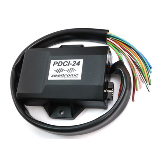
PDCI-24 PROGRAMMABLE CDI IGNITION
TECHNICAL DATA
Limit values:
- minimum revs
- maximum revs
- minimum supply voltage
- maximum supply voltage
- stand-by current draw
- current draw at 1300 RPM
- current draw at 12000 RPM
- maximum continuous current for shift light and power jet output
- peak current for shift light and power jet output
- constant spark energy from idle to 13000 RPM
Circuit is protected against reverse supply voltage (wrong connection).
Features:
- fast power-up (also starts only with condenser)
- full power starting spark energy already at 7Volts power supply
- one isolated input (pickup)
- two independent ignition coil outputs
- individual advance/retard of each output
- store and load function for two ignition maps
- external switch for changing ignition map while riding
- TPS input (Throttle Position Sensor)
- shift light output
- 2 power jet outputs
- duty cycle solenoid output (for regulating A/F ratio on some carburettors)
- quick shift (shift kill)
- soft rev limit (three stage rev limit)
- reduced spark at high revs with closed throttle (TCT mode)
- tachometer output
- easy and fast programming on the field, via hand held programmer
- programming while machine running - you can immediately see effects
- each curve can be set in 4 to 12 curve points
- 3D interpolated ignition map, if TPS selected
- signal delay compensation
USER MANUAL
- 1 -
200 RPM
20000 RPM
7 Volts
18 Volts
< 0.05 Amp
< 0.3 Amp
< 1.5 Amp
1 Amp
5 Amp
>35mJ
Advertisement

Subscribe to Our Youtube Channel
Related Manuals for zeeltronic PDCI-24


Summary of Contents for zeeltronic PDCI-24
- Page 1 15.03.2011 program version: 20.140311 USER MANUAL PDCI-24 PROGRAMMABLE CDI IGNITION TECHNICAL DATA Limit values: - minimum revs 200 RPM - maximum revs 20000 RPM - minimum supply voltage 7 Volts - maximum supply voltage 18 Volts - stand-by current draw <...
- Page 2 - instant monitoring of rev's and angle, via LCD(hand held programmer) - fast processing for high accuracy - delays from 1us - timing calculation for every 1 RPM change (1000, 1002, .. , 9805, 9806, ...) Very important! Resistor spark plugs must be used, because they produce less electromagnetic disturbances. Danger of electric shock! Avoid connecting PDCI to 12V power supply, before connecting it to ignition coil.
- Page 3 LOAD IGN. MAP Move to Load Ign. Map with pressing + or - and then press enter . Now you can select number of saved ignition map, with pressing + or - and then press enter . SAVE IGN. MAP Move to Save Ign.
- Page 4 Important! To avoid wrong processing, don't make unreasonable curve course. Every time you make any changes to ignition curve, it is automatically saved to number #0. Later you can save it to any other number #1 or #2. Ignition Map Example: 5.2.
- Page 5 ADVANCE 1 With this setting is possible to advance, or retard ignition map only on ignition coil output 1. When setting is positive, then ignition map is advanced and when setting is negative than, ignition map is retarded. Ignition map is unchanged, with setting 0.0deg. Enter menu and move to Advance, with pressing + or - and then press enter .
- Page 6 10.2. SMART SHIFT Smart shift function automatically adjusts kill time for different revs. Shift kill time must be always set, as basic kill time. Enter Quich Shift menu and move to Smart Shift with pressing + or - and then press enter. Now you can enable, or disable function with pressing + or - and then press enter .
- Page 7 Example: Power jet 1 ON (RPM) = 8000rpm Power jet 1 OFF (RPM) = 10000rpm Power jet 1 ON (TPS) = 70%TPS power jet 1 OFF (TPS) = 90%TPS Power jet is switched on when revs are between 8000-10000rpm and throttle position is between 70-90%, otherwise power jet is switched off.
- Page 8 15.1. OUTPUT TYPE Solenoid output function can be configured as Power Jet 2, or Duty Solenoid. Duty solenoid is used for adjusting A/F ratio on some carburettors. Enter Solenoid Output. menu and move to Output type with pressing + or - and then press enter .
- Page 9 Set TPS close [0%] (if TPS enabled) For correct operation, TPS close position must be calibrated! Move to TPS close [0%] with pressing + or - and then press enter. Leave throttle at close position and confirm calibrating with pressing enter , or exit calibration with pressing - .
- Page 10 IGNITION TEST Move to Ignition Test with pressing + , or - and then press enter . Multiple sparks will be generated at sparkplug 1 and after about second at sparkplug 2. Ignition test is available only when engine not running. MECHANICAL SETTINGS (Static Angle) Static Angle is ignition advance angle, set with stator (generator).
Need help?
Do you have a question about the PDCI-24 and is the answer not in the manual?
Questions and answers