Table of Contents
Advertisement
Quick Links
CL-OPT01_R/T
User Manual
Version 1.2
ⓒ 2005 DAQ SYSTEM Co., Ltd. All rights reserved.
Microsoft® is a registered trademark; Windows®, Windows NT®, Windows XP®, Windows 7®, Windows 8®, Windows 10®
All other trademarks or intellectual property mentioned herein belongs to their respective owners.
Information furnished by DAQ SYSTEM is believed to be accurate and reliable, However, no responsibility is assumed by DAQ SYSTEM for its use, nor
for any infringements of patents or other rights of third parties which may result from its use. No license is granted by implication or otherwise under
any patent or copyrights of DAQ SYSTEM.
The information in this document is subject to change without notice and no part of this document may be copied or reproduced without the prior
written consent.
Advertisement
Table of Contents

Related Manuals for DAQ system CL-OPT01-R


Summary of Contents for DAQ system CL-OPT01-R
- Page 1 All other trademarks or intellectual property mentioned herein belongs to their respective owners. Information furnished by DAQ SYSTEM is believed to be accurate and reliable, However, no responsibility is assumed by DAQ SYSTEM for its use, nor for any infringements of patents or other rights of third parties which may result from its use. No license is granted by implication or otherwise under any patent or copyrights of DAQ SYSTEM.
-
Page 2: Table Of Contents
CL-OPT01 User’s Manual Contents 1. CL-OPT01 Introduction ---------------------------------------------------------- 2. CL-OPT01_R Functions ------------------------------------------------------------- J2 Connector --------------------------------------------------------------------------- 2-2 J4 Connector --------------------------------------------------------------------------------- 2-3 JP1 Connector ------------------------------------------------------------------------ - 2-4 SW1 Switch --------------------------------------------------------------------------------- 2-5 SW2 Switch ------------------------------------------------------------------------ 2-6 CN1, CN2(SFP) Connector ----------------------------------------------------------------- 3. CL-OPT01_T Functions ------------------------------------------------------------ J2 Connector ---------------------------------------------------------------------------... -
Page 3: Cl-Opt01 Introduction
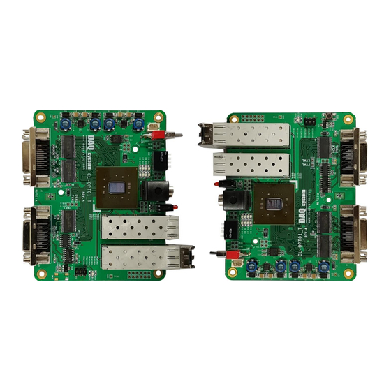
CL-OPT01 User’s Manual 1. CL-OPT01 Introduction The CL-OPT01_R board converts the image signal from the Camera Link camera into light and transmits it to the CL-OPT01_T board, which is the light receiving board. The CL-OPT01_T board receives the optical signal and outputs the camera link signal to the frame grabber. [Figure 1-1] shows the optical connection between CL-OPT01_R and CL-OPT01_T board. - Page 4 CL-OPT01 User’s Manual [Figure 1-2. CL-OPT01_R & PCIe-OPT01 Connection] [Figure 1-3. CL-OPT01_R/T와 USB3-FRM13(Frame Grabber)]...
- Page 5 CL-OPT01 User’s Manual [Figure 1-2] shows the direct connection of CL-OPT01_R to PCIe-OPT01, which is an optical-receiving frame grabber. Because Fiber Protocol is our standard, it cannot be used in connection with other optical boards. [Figure 1-3] and [Figure 1-4] show the connection between the CL-OPT01_R/T board, the USB3.0 interface, the USB3-FRM13 board, and the PCI Express interface, PCIe-FRM24, our frame grabber.
-
Page 6: Cl-Opt01_R Functions
CL-OPT01 User’s Manual 2. CL-OPT01_R Functions The names and functions of the CL-OPT1_R are as follows. [Figure 2-1. Outline drawing of CL-OPT01_R] The operation of the LED is as follows. J3 GREEN LED turns on when optical channel (# 0) is detected. J3 RED LED turns on when optical channel (# 1) is detected. - Page 7 CL-OPT01 User’s Manual J2 Connector (MDR-26 Connector for full/Mediun) The figure below shows the pin map of the J2 connector of the board used when using Base or Medium/Full Configuration Camera Link. All pin specifications are input/output based on the Camera Link standard, so please refer to the Camera Link standard document for details.
-
Page 8: J2 Connector
CL-OPT01 User’s Manual [Table 1. J2 Connector] Name Description Remark Inner Shield Cable shield Z3+- Camera link LVDS receive data11+ - ZCLK+ Camera link LVDS receive clock+ Z2+- Camera link LVDS receive data10+ Camera link LVDS receive data9+ Camera link LVDS receive data8+ TERMI-- Serial to Camera- Camera link LVDS receive data7+... - Page 9 CL-OPT01 User’s Manual J4 Connector (MDR-26 Connector for Base) The figure below shows the pin map of the J4 connector of the board used when using the Base Configuration Camera Link. All pin specifications are input/output based on the Camera Link standard, so please refer to the Camera Link standard document for details.
-
Page 10: J4 Connector
CL-OPT01 User’s Manual [Table 2. J4 Connector] Name Description Remark Inner Shield Cable shield CC4- Camera Control output 4- Minimum interval 6us or more CC3+ Camera Control output 3+ Minimum interval 6us or more CC2-- Camera Control output 2- Minimum interval 6us or more CC1+ Camera Control output 1+... -
Page 11: Jp1 Connector
CL-OPT01 User’s Manual JP1 Connector This is an external 12V DC power connector. (HR10-7R-6S-RA) [Figure 2-4. JP1 Connector] SW1 Switch It is a 12V DV external power switch. SW_T_SPOT +12V V_IN_12V [Figure 2-5. SW1]... -
Page 12: Sw2 Switch
CL-OPT01 User’s Manual SW2 Switch It is a camera setup mode selection switch. [Figure 2-6. Switch SW2] Switch #1 : 10Tap setting. ON : 10 Tap OFF : 8 Tap Note) In case of setting as 10Tap, one more optical module must be inserted. Switch #2 : Set the Baud Rate. -
Page 13: Cn1, Cn2(Sfp) Connector
CL-OPT01 User’s Manual 2-6 CN1, CN2 (SFP) Connector In the case of CL-OPT01_R, an SFP (Small Form Factor Pluggable) connector is used as a Fiber- Transmission Transceiver device. The SFP transceiver is designed to support various optical transmissions such as SONET, Gigabit Ethernet, and Fiber Channel. It supports hot-pluggable transceiver and can be connected to network device motherboard with fiber or copper networking cable. - Page 14 CL-OPT01 User’s Manual 3. CL-OPT01_T Connector The names and functions of CL-OPT1_T are described as follows. [Figure 3-1. CL-OPT01_T Layout] The operation of the LED is as follows. The J3 GREEN LED turns on when a Fiber Channel (#0) is detected. The J3 RED LED turns on when Fiber Channel (#1) is detected.
- Page 15 CL-OPT01 User’s Manual J2 Connector (MDR-26 Connector for full/Medium) The figure below shows the pin map of the J2 connector of the CL-OPT01_T board, which is a Camera Link output board. All pin specifications are input/output based on the Camera Link standard, so please refer to the Camera Link standard document for details.
-
Page 16: J2 Connector
CL-OPT01 User’s Manual [Table 3. J2 Connector] Name Description Remark Inner Shield Cable shield Camera link LVDS receive data4- Camera link LVDS receive data5- Camera link LVDS receive data6- YCLK- Camera link LVDS receive clock- Camera link LVDS receive data7- TERMI+ Serial to Camera+ Z0--... - Page 17 CL-OPT01 User’s Manual 3-2. J4 Connector (MDR-26 Connector for Base) The figure below shows the pin map of the J4 connector of the board used when using the Base Configuration Camera Link. All pin specifications are input/output based on the Camera Link standard, so please refer to the Camera Link standard document for details.
-
Page 18: J4 Connector
CL-OPT01 User’s Manual [Table 4. J4 Connector] Name Description Remark Inner Shield Cable shield Camera link LVDS transmit data0- Camera link LVDS transmit data1- Camera link LVDS transmit data2- Xclk- Camera link LVDS transmit clock- Camera link LVDS transmit data3- SerTC+ Serial to Camera+ 9600bps... -
Page 19: Jp1 Connector
CL-OPT01 User’s Manual JP1 Connector This is an external 12V DC power connector.. (HR10-7R-6S-RA) [Figure 3-4. JP1 Connector] SW1 Switch This is a 12V DV external power switch. SW_T_SPOT +12V V_IN_12V [Figure 3-5. SW1 switch]... -
Page 20: Sw2 Switch
CL-OPT01 User’s Manual SW2 Switch It is a camera setup mode selection switch. [Figure 3-6. SW2 switch] Switch #1 : 10Tap setting. ON : 10 Tap OFF : 8 Tap Note) In case of setting as 10Tap, one more optical module must be inserted. Switch #2 : Set the Baud Rate. -
Page 21: Cn1, Cn2(Sfp) Connector
CL-OPT01 User’s Manual 4-6 CN1, CN2 (SFP) Connector In the case of CL-OPT01_T, an SFP (Small Form Factor Pluggable) connector is used as a Fiber- Transmission Transceiver device. The SFP transceiver is designed to support various optical transmissions such as SONET, Gigabit Ethernet, and Fiber Channel. It supports hot-pluggable transceiver and can be connected to network device motherboard with fiber or copper networking cable. -
Page 22: Appendix
CL-OPT01 User’s Manual Appendix A-1 Board Size The external dimensions of the CL-OPT01_R/CL-OPT01_T board are as follows. < Top View >... -
Page 23: Repair Regulations
(3) All DAQ SYSTEM products have a one-year warranty. -. The warranty period is counted from the date the product is shipped from DAQ SYSTEM. -. Peripherals and third-party products not manufactured by DAQ SYSTEM are covered by the manufacturer's warranty. - Page 24 CL-OPT01 User’s Manual MEMO Contact Point Web sit : https://www.daqsystem.com Email : postmaster@daqsystem.com...
Need help?
Do you have a question about the CL-OPT01-R and is the answer not in the manual?
Questions and answers