
Subscribe to Our Youtube Channel
Related Manuals for Ruijie Reyee RG-ES126FGS-LP


Summary of Contents for Ruijie Reyee RG-ES126FGS-LP
- Page 1 Ruijie Reyee RG-ES126FGS- LP Switch Installation Guide Document Version: V1.2 Date: 2024.07.22 Copyright © 2024 Ruijie Networks...
- Page 2 All rights are reserved in this document and this statement. Any reproduction, excerption, backup, modification, transmission, translation or commercial use of this document or any portion of this document, in any form or by any means, without the prior written consent of Ruijie Networks is prohibited.
-
Page 3: Preface
Intended Audience This document is intended for: Network engineers Technical support and servicing engineers Network administrators Technical Support The official website of Ruijie Reyee: https://reyee.ruijie.com Technical Support Website: https://reyee.ruijie.com/en-global/support Case Portal: https://www.ruijienetworks.com/support/caseportal Community: https://community.ruijienetworks.com... - Page 4 Note This manual provides the device installation steps, hardware troubleshooting, module technical specifications, and specifications and usage guidelines for cables and connectors. It is intended for the users who have some experience in installing and maintaining network hardware. At the same time, it is assumed that the users are already familiar with the related terms and concepts.
-
Page 5: Table Of Contents
Contents Preface ..............................I 1 Product Overview ..........................1 1.1 Package Contents........................1 1.2 Product Appearance ........................2 1.2.1 Front Panel ........................2 1.2.2 Rear Panel ........................3 1.3 Technical Specifications ......................4 1.4 Cooling ............................5 2 Preparing for Installation ........................6 2.1 Safety Precautions ........................ - Page 6 2.2.7 Anti-interference Requirements ................... 10 2.2.8 Lightning Protection Requirements ................10 2.2.9 Installation Site Requirement ..................11 2.3 Rack Installation Requirements ....................11 2.4 Tools ............................12 3 Installing the Switch ......................... 13 3.1 Before You Begin ........................13 3.2 Precautions ..........................13 3.3 Mounting the Switch ........................
- Page 7 5.3 Lightning Protection ......................... 22 5.3.1 Installing AC Power Arrester (lightning protection cable row) ........22 5.3.2 Installing the Ethernet Port Arrester ................23...
-
Page 8: Product Overview
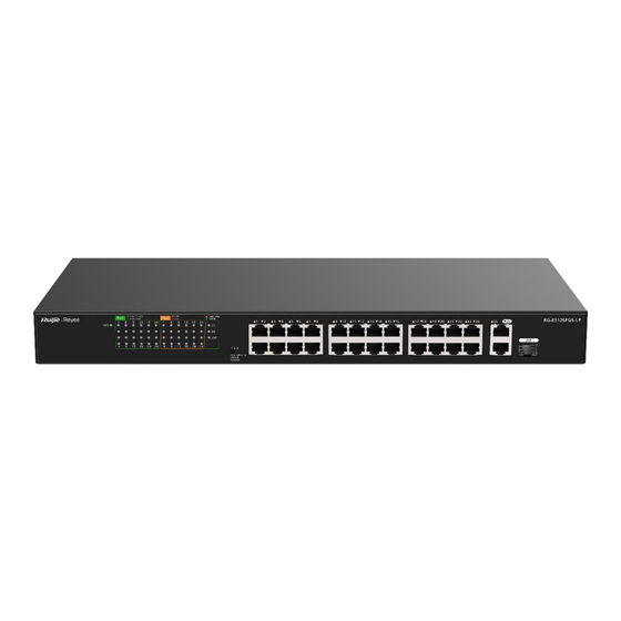
Installation Guide Product Overview Product Overview RG-ES126FGS-LP is a PoE switch with high performance and multiple working modes. The switch provides 24 10/100 Mbps self-adaptive Ethernet RJ45 ports, one 10/100/1000 Mbps self-adaptive Ethernet RJ45 port, and one GE combo port. All ports have line-rate forwarding performance, contributing to greater network flexibility. Featuring highly-integrated design and easy operation, the device is applicable for security monitoring and Wi- Fi hotspots arrangement. -
Page 9: Product Appearance
Installation Guide Product Overview Product Appearance The RG-ES126FGS-LP switch provides 24 10/100 Base-TX self-adaptive Ethernet ports, one 10/100/1000 Base-TX GE port, one 10/100/1000 Base-TX combo port, one DIP switch, one system status LED, and other LEDs on the front panel. On the rear panel of the switch, there is an AC power plug and a grounding stud. Figure 1-1 Appearance of a RG-ES126FGS-LP Switch 1.2.1... -
Page 10: Rear Panel
Installation Guide Product Overview Item Description Flashing green: The port is transmitting and receiving data at 1000 Mbps. Off: The port is not connected. 10/100/1000 Solid orange: The port has made a successful 10/100 Mbps link. Flashing orange: The port is transmitting and receiving data at Base-TX Combo 10/100 Mbps. -
Page 11: Technical Specifications
Installation Guide Product Overview Table 1-3 Rear Panel Specifications Item Description Grounding Stud Connect the grounding stud to the protection ground with the grounding cable to provide grounding protection. AC Input Plug Connect the power cord to the AC input plug to power on the switch. Technical Specifications Table 1-4 Technical Specifications of a RG-ES126FGS-LP Switch... -
Page 12: Cooling
Installation Guide Product Overview Model RG-ES126FGS-LP Operating 10% to 90% RH (non-condensing) Humidity Storage Humidity 5% to 95% RH (non-condensing) Port Surge Common Mode 4 kV Protection Number of Fans One fan Airflow Direction Left-to-right airflow Certification Ground Leakage ≤ 3.5 mA Current Dimensions 440 mm x 214.9 mm x 44 mm(17.32 in. -
Page 13: Preparing For Installation
Installation Guide Preparing for Installation Preparing for Installation Safety Precautions Note To avoid device damage and physical injury, please read the safety precautions carefully before installing the device. The following safety precautions may not cover all possible dangers. 2.1.1 General Safety Precautions ... -
Page 14: Electrostatic Discharge Safety
Installation Guide Preparing for Installation Select a correct leakage protector (also referred to as “leakage current switch” or “leakage current breaker”) for the power supply system. When there is a risk of leakage and electric shock, the power supply is automatically disconnected. -
Page 15: Installation Environment Requirements
Installation Guide Preparing for Installation Figure 2-1 Laser Product Warning Warning Do not approach or look directly into any optical port under any circumstances. This may cause permanent damage to your eyes. Installation Environment Requirements The device must be installed indoors. To ensure its normal operation and prolonged service life, the installation site must meet the following requirements. -
Page 16: Cleanliness Requirements
Installation Guide Preparing for Installation device and severely affecting its service life. Note The ambient temperature and humidity of the device are measured at the point that is 1.5 m (59.06 in.) above the floor and 0.4 m (15.75 in.) before the device rack when there is no protective plate in front or at the back of the rack. -
Page 17: Grounding Requirements
Installation Guide Preparing for Installation 2.2.6 Grounding Requirements A proper grounding system is the basis for stable and reliable running and is indispensable for preventing lightning strikes and interference. Carefully check the grounding conditions at the installation site according to the grounding specifications, and complete grounding properly based on the actual situation. -
Page 18: Installation Site Requirement
Installation Guide Preparing for Installation prevention for the power supply. 2.2.9 Installation Site Requirement Regardless of whether the device is installed into a rack or on a workbench, the following conditions must be met: Maintain a proper clearance around the air inlets and ventilation openings for heat dissipation. ... -
Page 19: Tools
Installation Guide Preparing for Installation (5) A grounding lug is installed properly on the rack to ensure that the device is fully grounded. (6) The rack is well ventilated and the porosity of the front and rear panels is greater than 50%. Tools Table 2-3 Tools... -
Page 20: Installing The Switch
Installation Guide Installing the Switch Installing the Switch Caution Ensure that requirements in Chapter 2 are all met. Before You Begin The installation site provides sufficient space for heat dissipation. The installation site meets the temperature and humidity requirements of the device. ... -
Page 21: Rack Installation Requirements
Installation Guide Installing the Switch 3.3.1 Rack Installation Requirements (1) Before installing the rack, plan the available space for the rack. Reserve sufficient space for the front and rear doors of the rack for device maintenance. (2) Mount and fasten the rack at the designed location as planned. (3) Install the appropriate cable management bracket and cables. -
Page 22: Grounding The Switch
Installation Guide Installing the Switch Figure 3-2 Securing the Switch to the Rack Grounding the Switch Connect the grounding cable to the grounding stud on the back panel of the device. Note The grounding cable is not delivered with the switch and should be purchased separately. Connecting the Cables Warning Please use the power cord delivered with the device to prevent accidents. -
Page 23: Debugging
Installation Guide Debugging Verify that a minimum clearance of 10 cm (3.94 in.) is maintained around the device for air circulation. Debugging Powering on the Switch 4.1.1 Checklist Before Power-On The switch is connected to earth ground. The power cord is properly connected. - Page 24 Installation Guide Debugging (2) Tap the Topology button, and select the existing managed device. To add an unmanaged downlink switch by scanning its QR-code, select Scan to Add. (3) After the device is detected, select its uplink port. And the device is added successfully.
-
Page 25: Adding Unmanaged Device Manually
Installation Guide Debugging 4.2.2 Adding Unmanaged Device Manually (1) Tap Topology to enter the topology page. (2) Tap the Topology button, and select the existing managed device. To add an unmanaged downlink switch manually, select Manually Add. (3) Select the device model and its uplink port, and the device is added successfully. -
Page 26: Appendix
Installation Guide Appendix Appendix Connectors and Media 1000BASE-T/100BASE-TX/10BASE-T The 1000BASE-T/100BASE-TX/10BASE-T is a 10/100/1000 Mbps self-adaptive Ethernet port that supports auto MDI/MDIX Crossover. Compliant with IEEE 802.3ab, 1000BASE-T requires Category 5 or Category 5e 100-ohm UTP or STP (STP is recommended) with a maximum distance of 100 m (328.08 ft). - Page 27 Installation Guide Appendix Figure 5-2 100BASE-TX/10BASE-T Pin Assignments Figure 5-3 shows wiring of straight-through and crossover cables for 100BASE-TX/10BASE-T. Figure 5-3 100BASE-TX/10BASE-T Twisted Pair Connection Fiber-Optic Cable Connection Please choose SMF or MMF optic cables according to the module types. Figure 5-4 Fiber-Optic Cable Connection...
-
Page 28: Mini-Gbic And Sfp Modules
Installation Guide Appendix Mini-GBIC and SFP Modules We provide GE SFP modules (Mini-GBIC modules) according to the SFP port types. You can select the module to fit your specific needs. The following models and technical specifications of some GE SFP modules are listed for your reference. -
Page 29: Lightning Protection
Installation Guide Appendix Mini-GBIC- CAT 5 100 m Lightning Protection 5.3.1 Installing AC Power Arrester (lightning protection cable row) The AC power port must be connected to an external lightning protection power strip to prevent the switch from being struck by lightning when the AC power cord is introduced from the outdoor and directly connected to the power port of the switch. - Page 30 Installation Guide Appendix polarity of the arrester power cord should be reversed. In this case, open the power arrester and rectify the polarity of the connection. If the LED is still Red, the arrester PE terminal has not been grounded. 5.3.2 Installing the Ethernet Port Arrester Please connect an Ethernet port arrester to the switch to prevent the damage by lightning before...
- Page 31 Installation Guide Appendix The Ethernet port arrester is not delivered with the switch. Please purchase it based on actual requirements. During the actual installation, pay attention to the following items: Reversed installation direction of the arrester. Connect the external Ethernet cable to the IN end and connect the Ethernet port of the switch to the OUT end.
Need help?
Do you have a question about the Reyee RG-ES126FGS-LP and is the answer not in the manual?
Questions and answers