Table of Contents
Advertisement
Quick Links
60 class
■組立前に必ずこの説明書を最後まで、よくお読みになり、
正しくお使い下さい。
■この説明書は「TOWCOBRA」専用の部分についてのも
のです。「60スケールシリーズ」共通の部分は、メカニ
カルキット説明書をお読み下さい。特に「安全のために
必ずお守り下さい」は、飛行前に必ず読んで下さい。
■この説明書は、大切にお手元に保管して下さい。
※製品改良のため、予告なく仕様を変更する場合があります。
■Please read this manual in its entirety before attempting
to assemble the helicopter.
■This
manual
explains
TOWCOBRA. For parts common to the 60 scale series,
please read the mechanical kit manual. In particular,
please read the section entitled 'Always follow these
rules for safety' before attempting to fly the helicopter.
■Keep this manual in a safe place.
※Changes in product specifications may be effected
without notice.
the
parts
exclusive
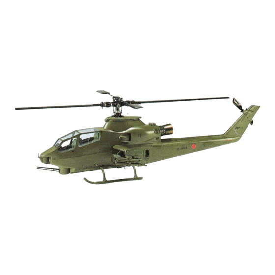
SCALE HELICOPTER
TOWCOBRA
AH-1S
BODY KIT
INSTRUCTION MANUAL
to
マフラーは0414-263 S60-II後方排気マフラー
(ボックスタイプ)をご使用下さい。
その他のマフラーは使用できません。
Use a 0414-263 S60-II rear exhaust muffler
(box type). Other mufflers can not be used.
MADE IN JAPAN
III
取扱説明書
2002
Advertisement
Table of Contents

Related Manuals for Hirobo TOWCOBRA AH-1S III BODY KIT


Summary of Contents for Hirobo TOWCOBRA AH-1S III BODY KIT
- Page 1 60 class SCALE HELICOPTER TOWCOBRA AH-1S BODY KIT INSTRUCTION MANUAL 取扱説明書 ■組立前に必ずこの説明書を最後まで、よくお読みになり、 正しくお使い下さい。 ■この説明書は「TOWCOBRA」専用の部分についてのも のです。「60スケールシリーズ」共通の部分は、メカニ カルキット説明書をお読み下さい。特に「安全のために 必ずお守り下さい」は、飛行前に必ず読んで下さい。 ■この説明書は、大切にお手元に保管して下さい。 ※製品改良のため、予告なく仕様を変更する場合があります。 ■Please read this manual in its entirety before attempting to assemble the helicopter. ■This manual explains parts exclusive マフラーは0414-263 S60-II後方排気マフラー TOWCOBRA. For parts common to the 60 scale series, (ボックスタイプ)をご使用下さい。...
-
Page 2: Table Of Contents
目 次 Contents トップカバーの取付 ............P.2 Attaching the top cover ............P.2 スキッドの組立・アンダーカバーの加工 ....... P.3 Skid assembly and undercover preparation ..... P.3 テールスキッドの取付 ............P.4 Attaching the tail skid ............P.4 エアインテークの取付 ............P.4 Attaching the air intake............P.4 水平尾翼の取付 ..............P.4 Attaching the horizontal tail fin .......... P.4 コクピット・トップカバーの組立 ........P.5 Cockpit and top cover assembly ........P.5 アクセサリーの取付 -1 ............P.6 Attaching the accessories-1 .......... -
Page 3: トップカバーの取付
トップカバーの取付 Attaching the top cover 片側 8ヶ所、左右計 16 本のビスで取付けます。 Attach the 16 screws (8 on each side). ① 図を参考に下部胴体に取付ビス位置をマジックペン ① Referring to the figure, mark the position of the screws 等で記します。 on the bottom of the body with a marker pen etc. ② 内側に補強ベニヤ 10 × 10mmを接着します。 接着に ② Attach a 10 × 10mm piece of reinforcement plywood はエポキシ(30 分以上硬化型)を使用します。接着前 to the inside with epoxy (30 minute hardening type). 補強ベニヤ …………… 16 に接着面をサンドペーパーでサンディングし、アル Sand the contact surfaces with sanding paper and wipe コールで油分を拭きとります。 any oil away with alcohol before attaching. ③ 上部下部胴体がピッタリ合う様に上部胴体外周をヤ ③ In order to ensure that the upper and lower halves of スリ等で修正します。 the body fit together perfectly, use a file to file the M2.6×6 ト ラスTS………… 16 ④... -
Page 4: スキッドの組立・アンダーカバーの加工
スキッドの組立・アンダーカバーの加工 Skid assembly and undercover preparation 組立後瞬間接着剤 を使用します。 M3×5SS ………………… 8 カットします Use cyanoacrylate Cut 8mm glue after assembling. 防振ゴム M2.6×6 ト ラスTS ………… 8 Shock absorbing M2.6×6 truss TS rubber M3×8TS ………………… 8 瞬間接着剤 Cyanoacrylate glue 90° 90° 64mm ボディとぴったり合う様にアンダーカバーを ヤスリ等で修正します。 In order to ensure that it fits the body perfectly, use a file to file the undercover. 直径 16mm カット (スキッドの取付けに合わせてカットする) Cut off Diameter 16mm (Cut in accordance with the attachment of the skid.) 前... -
Page 5: Attaching The Tail Skid
テールスキッドの取付 Attaching the tail skid テールスキッド取付用穴をあけます。 Tail skid mounting hole. テールスキッド Tail skid 幅 3 〜 5mm 10mm エポキシで固める Cement with epoxy glue 胴枠 Fuselage frame 胴枠 Fuselage frame エアインテークの取付 胴体内側より取り付ける。 Attaching the air intake Mount air intake from inside. [エアインテーク] [Air intake] 金網を適当な大きさにカットして、 内側から接着します。 Cut the suitable size of the wire net. カットする Cut off ケガキ線にあわせカット します。 (左側のみ) Cut along the mark-off line. (Left side only) 水平尾翼の取付 Attaching the horizontal tail fin φ 2 穴をあけます ボディにぴったり合うように、水平尾翼の接着面 Open φ 2 holes. をサンディングします。... -
Page 6: Cockpit And Top Cover Assembly
コクピット・トップカバーの組立 Cockpit and top cover assembly エポキシ 窓を抜き、金網を内側から接着します。 Epoxy Cut off the windows, adhere the wire nets from inside. エポキシ Epoxy カットします Cut off エポキシ Epoxy カットします Cut off エポキシ [コクピット] Epoxy [Cockpit] フード コックピットはケガキ線より多 Hood スティック(長) めにカットし、トップカバーに Stick (Long) 合わせてさらにカットします。 Cut the cockpit slightly more than (ス ティッ クはコ ック indicated by the mark-off line, and スティック(短) ピ ッ ト 下 面 か ら ス ク then ... -
Page 7: Attaching The Accessories-1
アクセサリーの取付 -1 Attaching the accessories -1 [レーダーサイト] [Rader sight] M3×10PH ……………… 2 M2ナ ッ ト ………………… 2 M2 nut エポキシ Epoxy M3 × 10PH M3ナ ッ ト ………………… 2 M3 ナット M3 nut M3 nut M2 ナット M2 nut エポキシ Epoxy カットする φ 1.8 穴をあけます。 Cut off φ 3 穴をあけます。 Open a φ... -
Page 8: Tail Gear Assembly
ユニバーサルピン Universal pin M3 × 5SS ● テールブレードの取付 Attachment of tail rotor blade. ① テールブレードのバランスを取ります。 テールブレード ② テールブレードを M3 × 16CS、M3 ナイロンナット Tail rotor blade で固定します。この時、テールブレードが手で軽く 動く程度に締めて下さい。 ① Balance the tail blades. ② Secure each tail blade with a M3×16 CS and M3 lock nut. M3 × 16CS Fasten the tail blades tight enough so they can be moved slightly by hand. M3 ナイロンナット M3 nylon nut 軽い方にテープ等を巻く。 Wind tape at a lighter side. 注意 Caution テールブレードは必ず純正品を使用して下さい。 純正品以外の物を使用しますと、破損、墜落の恐れがあります。 Always use Hirobo brand tail blades for best performance. If another brand is used, damage or a crash may result. -
Page 9: Drive Shaft Assembly
ドライブシャフトの組立 Drive shaft assembly ① アングルミッション ASSYを M2.6×8CSで固定しま ① Fix the angle transmission assembly with the M2.6 × す。 (仮組) 8CS. (Temporary assembly) ② フレーム、 テールドライブASSY P=132、 テールドラ ② Temporarily assemble the frame, tail drive assembly M2.6×8CS ……………… 4 イブ ASSY P=410、テールユニット ASSY、テールド P=132, tail drive assembly P=410, tail unit assembly and ライブ ASSY P=121 の仮組をします。 tail drive assembly P=121. Pass the tail drive assembly テールドライブ ASSY P=410 を胴枠に通し、スムー P=410 through the fuselage frame, and decide the M3×15皿PH …………… 4 ズに回転するようにテールドライブ ASSY P=410 と positions of the tail drive assembly P=381 and angle M3×15 coutersunk screw アングルミッション... -
Page 10: Attaching The Tail And Rudder Linkage
テールとラダーリンケージの取付 Attaching the tail and rudder linkage ① ラダーサーボを取付けます。 ① Attach the rudder servo. M2×6CS …………………1 EX φ 5ボール ………………1 M2.6 × 16TS-2 座金付 EX φ 5 ball φ 1.7FW……………………1 サーボの大きさに合わせて カットします。 Cut to match the size of the M2ナ ッ ト……………………1 servo. M2 nut サーボマウント(B) Servo mount (B) ② φ 1.2 × 1200 ピアノ線は、ニュートラルをチェッ クして、長さを決定してからカットして下さい。 ③... -
Page 11: Attaching The Main Frame
メインフレームの取付 Attaching the main frame ① 胴体にメインフレームを組込みます。フレームを固 ① Install the main frame into the fuselage. Before 定する前にテールドライブ ASSY P=132 をテールド mounting the frame, insert the tail drive assembly ライブ ASSY P=410 に差し込んでおきます。 P=132 into tail drive assembly P=410. M3×40PH ……………… 2 ユニバーサルハブの中に必ずグリスを 塗布して下さい。 Apply grease to the inside of the universal hub. M3×22CS ……………… 6 テールドライブ ASSY P=410 Tail drive assembly P=410 M3ナイ ロ ンナ ッ ト ………… 2 テールドライブ ASSY P=132 M3 nylon nut Tail drive assembly P=132 M5ナイ... -
Page 12: Attaching The Accessories-2
アクセサリーの取付 -2 Attaching the accessories -2 [トウランチャー] [ロケット弾ポッド] [Tow launcher] [Rocket bomb pod] 接着(瞬間接着剤) Adhere (quick drying glue) 8 本作ります。 瞬間 Make eight sets. Quick drying glue ランチャーホルダー Launcher holder 接着 M3×35PH …………… 12 Adhere ランチャー・ホルダー・フック セット作ります。 Make two sets. 各々個別に塗装後、 組立、 接着 M3×8 ト ラスPH ………… 2 します。 (細かい所が塗装出来 M8×8 truss PH Assemble the launcher, the holder and ない為) the hook separately after painting, and フック Hook then bond them together. (To avoid the M2×8TS …………………... -
Page 13: Attaching The Covers
各カバーの取付 Attaching the covers テールミッションに合わせて カットします。 Cut to match the tail gear. M2.6×6 ト ラスTS ………… 4 M2.6 × 6 トラス TS M2.6×6 truss TS M2.6 × 6 truss TS M1.7×5TS ……………… 4 φ 1.8 穴をあけます Open a φ 1.8 hole. ローターヘッド Assy Rotor head assembly プラパーツ Plastic parts トップカバー Top cover M1.7 × 5TS ミッションカバー Mission cover ボディ Body M2.6 ×... -
Page 14: Affixing The Decals
デカールの貼付 Affixing the decals [Determining the center of gravity] [重心位置について] ローターヘッドを持ち上げた時、スキッドパイプが Load the ballast such as lead into the nose so that the skid 床から水平に持ち上がるまで機首に鉛等のバラスト pipe can be lifted level with the floor when the rotor head を積んで下さい。 is up. 陸上自衛隊仕様 Ground Self-Defense Force specifications アメリカ軍仕様 US military specifications... -
Page 15: Painting
塗装について Painting 組上がった機体を一度分解して各部分ごとに塗装しま First disassemble the completed fuselage and paint each す。 section individually. ① FRP 部品はキズ、ピンホール等の修正後石鹸水と# ① FRP parts should be sanded smooth with soapy water 300 〜 400 位の耐水ペーパーでまんべんなく磨きま and 300-400 grit sandpaper after pinholes and other す。磨きすぎるとピンホールが出て来ますので注意 flaws have been fixed. が必要です。 Be sure not to polish them too hard because new ② 一度薄目に溶いた色塗料を軽く吹き付け、乾かしま pinholes may be made. すとピンホール等が良く見えますので大きなものは ② Lightly spraying a primer coat of paint and then letting ポリパテ、小さなピンホール(1 〜 2ヶ)であれば瞬 it dry completely highlights the appearance of 間接着剤等で押さえ、また磨いておきます。 pinholes and other flaws. Along with polishing, larger ③ もう一度軽く塗ってピンホール等のチェックをしま pinholes should be filled with filling putty and smaller す。... - Page 16 Data sheet Transmitter:FUTABA FF9-H 1ch(AIL) 2ch(ELE) 3ch(THR) 4ch(RUD) 5ch(GYR) 6ch(PIT) (R/U) 100% 100% 100% 100% 100% 100% (L/D) 100% 100% 100% 100% 100% 100% 100% ----- 100% ----- ----- ----- 100% ----- ----- ----- ----- ----- ----- ----- ----- NORM NORM NORM NORM...
- Page 17 補修パーツについて ※ Spare parts are available for direct sales from HIROBO, but only in Japan. ●補修パーツのご購入につきましては、キットを購入された模型店へコード番号と名称を言ってお買い求め下さい。 ●上記の方法で購入が困難な場合は、直接当社へ下記要領にてお申し込み下さい。 ●お届け 商品は小包にて、ご注文受付日から3日〜7日後にお届けいたします。 週末、年末年始、GW、お盆休み中のご注文は、休み明けから3日〜7日後とさせていただきます。 月初めは棚卸しのため1日〜3日ほど余分にお時間をいただくこともあります。あらかじめご了承下さい。 ●商品の交換 商品の不良、配送上の破損、ご注文と違う商品が届いた場合は、お手数ですが商品到着8日以内にお電話 (0847-40-0088)パーツ係までご連絡の上、ご返送下さい。返送料は当社で負担いたします。 お客様のご都合による返品 ・ 交換は受け付けており ませんので、 コー ドNo、 品名、 数量を ご確認の上、 ご注文く ださい。 ※コードNo、品名は商品に表示してあります。商品が届いてすぐに内容をご確認ください。 ●お申し込み方法(現金書留または代金引換にてお受けしております) 代金引換 現金書留 注文書同封の上、お申し込みください。...
- Page 18 2532-041 2500-057 2539-006 2506-019 0404-318 0404-318 0404-320 0404-566 0404-322 2500-065 0404-322 2524-003 0404-320 0404-321 2531-002 2500-065 0402-597 2505-013 0404-322 0404-231 2506-029 2506-005 0402-578 2500-061 2534-005 2500-068 2524-004 2505-006 2532-005 0404-316 0402-596 2500-068 0404-315 2505-006 0404-231 0404-314 2505-006 2531-003 2532-030 2531-001 2500-068 0414-249 0404-564...
- Page 19 コ ー ド 品 名 入 数 価 (円) 格 備 考 i t r y t ' テ ー ル ハ ウ ジ ン グ セ ッ ト 1式 l i a テ ー ル ブ レ ー ド ホ...
- Page 20 WARRING THIS AIRCRAFT WARRING THIS AIRCRAFT 0401-057 CONTAINS A CARTRIDGE ACTUA TED CONTAINS A CARTRIDGE ACTUA TED EMERGENCY ESCAPE SYSTEM EMERGENCY ESCAPE SYSTEM EQUIPPED WITH EXPLOSIVE DEVICES EQUIPPED WITH EXPLOSIVE DEVICES SEE TN 53 4520 270 28 SEE TN 53 4520 270 28 FOR COMPLETE INSTRUCTIONS FOR COMPLETE INSTRUCTIONS 0414-243 U.S.ARMY AH-1S U.S.ARMY SERIAL NO.22576 0404-414 SERVICE THIS AIRCRAFT WITH NIL-T-3824 GRADE CW2 STADY JP-4 AVIATION FUEL IF NOT AVAILABLE REFER TO TB33-9130-200-25 FOR PFC HILL ALTERNATE FUEL 0414-235 0414-256 AMMUNITION COMPARTMENT AMMUNITION COMPARTMENT 0414-040 HIROBO 2002 TOW COBRA NO.10879 0414-260 0414-041 0404-433...
- Page 21 コ ー ド 品 名 入 数 価 (円) 格 備 考 i t r y t ' ア ジ ャ ス ト ジ ョ イ ン ト 新 防 振 ゴ ム セ ッ ト 防 振 ゴ ム と...
- Page 24 726-0004 〒 HIROSHIMA-PREF., JAPAN. 〒726-0004 TEL: 0847 40-0088 FAX:45-7670 ( ) (代) TEL:0847-40-0088 FAX:0847-45-7670 http://model.hirobo.co.jp/ http//model.hirobo.co.jp/ 注意 Caution ①本書の内容の一部または全部を無断で転載することは禁止されています。 ②本書の内容については、将来予告なしに変更することがあります。 ③本書の内容について万全を期しておりますが、万一ご不審な点や誤り、記載もれなどお気付 きのことがありましたら、ご一報くださいますようお願いいたします。 ④運用した結果については③項にかかわらず責任を負いかねますので、ご了承ください。 ①Reproduction of this manual, or any part thereof is strictly prohibited. ②The contents of this manual are subject to change without prior notice.
Need help?
Do you have a question about the TOWCOBRA AH-1S III BODY KIT and is the answer not in the manual?
Questions and answers