Table of Contents
Advertisement
Quick Links
Advertisement
Table of Contents
Troubleshooting

Subscribe to Our Youtube Channel
Related Manuals for Sensata Magnum Energy CSW3012-X


Summary of Contents for Sensata Magnum Energy CSW3012-X
- Page 1 CSW3012-X Pure Sine Wave Inverter Owner’s Manual...
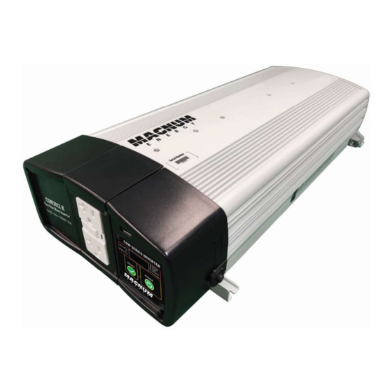
- Page 2 Thank you from all of us at Sensata Technologies for purchasing this CSW3012-X inverter. The CSW3012-X is under the Magnum Energy brand from Sensata Technologies. We understand that you have many purchasing options in the marketplace and are pleased that you have decided on this product.
- Page 3 Explosion hazard! DO NOT use this inverter in the vicinity of fl ammable fumes or gases (such as propane tanks or large engines). • These inverters contain no user-serviceable parts. See the Warranty section for how to handle service issues. © 2021 Sensata Technologies...
-
Page 4: Table Of Contents
Appendix B - Preventive/Periodic Maintenance ......38 Recommended Inverter and Battery Care ........38 RV/Marine Off -Season Storage ............38 Appendix C - Regulatory and FCC Information ......39 Appendix D - Limited Warranty ............ 40 How to Receive Warranty Service............ 40 © 2021 Sensata Technologies... - Page 5 Table 2-3, Appliance Power Consumption and Run Time ......13 Table 3-1, Display Functions/Statuses ..........25 Table 3-2, Inverter Settings .............. 27 Table 4-1, Inverter Error Codes ............29 Table 4-2, Troubleshooting ..............30 Table 5-1, CSW3012-X Specifications ..........35 © 2021 Sensata Technologies...
-
Page 6: 1.0 Introduction
Congratulations on your purchase of the CSW3012-X inverter. The CSW3012-X is a “pure” sine wave inverter with an internal transfer switch and is sold under the Magnum-Dimensions brand from Sensata Technologies. This unit is designed to be powerful, yet simple to operate, and will provide you with reliable AC power for trouble-free use. -
Page 7: Figure 1-2, Front Panel Features (Cover Removed)
#10 AWG (2.1 to 5.3 mm ) CU stranded wire. They use slotted head screws and have a recommended maximum tightening torque of 5 to 8 lbf-in (0.6 to 0.9 N-m). Figure 1-2, Front Panel Features (Cover Removed) © 2021 Sensata Technologies... -
Page 8: Figure 1-3, Back Panel Features
15. DC Positive Terminal (red) – the inverter’s connection to the positive terminal on the 12 VDC battery bank. 16. DC Negative Terminal (black) – the inverter’s connection to the negative terminal on the 12 VDC battery bank. Figure 1-3, Back Panel Features © 2021 Sensata Technologies... -
Page 9: How This Inverter Works
CSW3012-X provides you with all the advantages of a pure sine wave inverter at a much lower cost than many on the market. Square Wave Sine Wave Modified Sine Wave TIME Figure 1-4, AC Waveforms © 2021 Sensata Technologies... -
Page 10: 2.0 Installation
*** 2.1.3 Tools Required Installing the inverter is simple and requires the following: • Adjustable wrench (10-13 mm) • Level • Drill • #10 Mounting screws (x4) • Pencil • Drill bits • Phillips screwdriver © 2021 Sensata Technologies... -
Page 11: Figure 2-1, Basic System Diagram
L2/N2 = 20A max) Fuse Battery Bank Tools * Maximum pass-thru current from AC output terminals: L1/N1 output terminals = 30 amps, L2/N2 output terminals = 20 amps (in series with GFCI outlet). Figure 2-1, Basic System Diagram © 2021 Sensata Technologies... -
Page 12: Locating And Mounting The Inverter
Secure the inverter to the surface using the appropriate corrosion-resistant hardware. If this unit is used in a mobile application, you may want to place flexible washers or bushings between the mounting surface and the inverter’s mounting flanges to reduce vibration. © 2021 Sensata Technologies... -
Page 13: Figure 2-2, Approved Mounting Positions
Note: CSW3012-X cannot be mounted with DC terminals facing down. Figure 2-2, Approved Mounting Positions 16.7’’ (42.3 cm) 21.3’’ (54 cm) Back (DC Side) Front (AC Side) 4.5’’ (11.5 cm) Figure 2-3, CSW3012-X Dimensions © 2021 Sensata Technologies... -
Page 14: Wiring The Inverter - General Requirements
M8 x 1.25 16 to 21 lbf-ft DC Terminals 13 mm wrench Hex nuts (21.7 to 28.5 N-m) M6 x 1.0 79 to 96 lbf-in DC Ground 10 mm wrench Hex nut (8.9 to 10.9 N-m) © 2021 Sensata Technologies... -
Page 15: Dc Wiring
• Where DC wiring must cross AC or vice-versa, try to make the wires at the crossing point perpendicular (90 degrees) to one another. © 2021 Sensata Technologies... -
Page 16: Dc Wire Sizing
8 AWG copper. In some applications (i.e., Marine installations), the DC grounding conductor is required to be no less than one size smaller than the wire size of the DC positive/negative cables. © 2021 Sensata Technologies... -
Page 17: Dc Overcurrent Protection
. To reduce this risk, use an anti-seize lubricant, tighten the fasteners slowly (at low rpms) without interruption, and apply only light pressure. © 2021 Sensata Technologies... -
Page 18: Wiring The Battery Bank
2000 W N.R. 15 mins 34 mins 49 mins 1 hrs. 2500 W N.R. 11 mins 25 mins 37 mins 49 mins 3000 W N.R. N.R. 17 mins 27 mins 37 mins Note: N.R. - Not Recommended © 2021 Sensata Technologies... -
Page 19: Wiring The Inverter To The Battery Bank
Route an appropriately sized DC ground wire (see Table 2-2) from the inverter’s DC chassis ground connection to a dedicated system ground. Once the entire installation is complete and all connections verifi ed, close the fuse disconnect (or circuit breaker) to provide power to the inverter. © 2021 Sensata Technologies... -
Page 20: Figure 2-4, Dc Cable To Battery Terminals
M8-1.25 Hex nut Lock washer DC cable with ring lug CAUTION: Ensure nothing is placed between the DC terminal and the ring lug. CSW3012-X Inverter Inverter’s DC + terminal Figure 2-5, DC Cable to Inverter’s DC Terminals © 2021 Sensata Technologies... -
Page 21: Ac Wiring
#12 AWG (3.3 mm ) is recommended. Note: The AC 2 (L2/N2) output terminals are connected to the load side of the GFCI receptacle, and are under the influence of the receptacle’s “Test” and “Reset” buttons. © 2021 Sensata Technologies... -
Page 22: Ac Neutral To Safety Ground Bonding
By-Pass mode, the internal relay automatically opens the neutral-to-ground connection. This design keeps two neutral-to-ground connections from occurring at the same time, thereby preventing an electrical shock hazard between the vehicle/boat’s neutral and the external AC source’s neutral. © 2021 Sensata Technologies... -
Page 23: Ac Terminal Block Connections
L1/N1 output terminals (see Wiring the Inverter AC Output section on next page). 3. Connect the neutral (WHITE) from the main panel’s neutral busbar to the inverter’s AC input “N” terminal. © 2021 Sensata Technologies... - Page 24 3. After verifying all AC connections are correct, ensure all inverter AC terminals are torqued correctly. 4. Replace the AC wiring access cover and the covers on the main electrical/ distribution panel. © 2021 Sensata Technologies...
-
Page 25: Figure 2-6, Ac Wiring (20A By-Pass And Gfci Output))
AC input NOTE: In mobile installations, the neutral is typically not connected to ground in main panel. Main Panel Sub-Panel and Outlet (Utility/Generator (Inverter Loads) Input) Figure 2-6, AC Wiring (20A By-Pass and GFCI output)) © 2021 Sensata Technologies... -
Page 26: Figure 2-7, Ac Wiring (30A By-Pass)
(single pole) required to inverter AC input NOTE: In mobile installations, the neutral is typically not connected to ground in main panel. Main Panel Sub-Panel and Outlets (Utility/Generator (Inverter Loads) Input) Figure 2-7, AC Wiring (30A By-Pass) © 2021 Sensata Technologies... -
Page 27: 2.5.6 Removing The Display Panel
Figure 2-8. 6-conductor telephony type opposite colors top to bottom (tabs facing toward you) same same color color Figure 2-8, Remote Cable © 2021 Sensata Technologies... -
Page 28: Testing The Inverter
The inverter is now in Inverter mode. If the inverter passes all the steps, the inverter is ready for use. If it fails any of the steps, refer to the troubleshooting information in Sec- tion 4.0. © 2021 Sensata Technologies... -
Page 29: 3.0 Operation
By-Pass mode to Invert mode in less than 30 milliseconds. When switching from Invert mode to By-Pass mode, the inverter waits approximately 20 seconds to ensure the grid is stable (or the generator is up to speed) and then makes the transfer. © 2021 Sensata Technologies... -
Page 30: Display Panel Operation
Pass mode with PS4 setting—without the need to disconnect the AC input as per the PS1 setting. See Table 3-2 or Section 3.3.3. Select button – Used to check the inverter settings. Press the Select button several times to scroll down to view the inverter’s present setting. © 2021 Sensata Technologies... -
Page 31: Figure 3-2, Inverter Setting Flow Chart
Default Press x1 sec to Press x5 sec to set selection move to next menu and to exit to the next menu EXIT Function S et Menus Function Menus Figure 3-2, Inverter Setting Flow Chart © 2021 Sensata Technologies... -
Page 32: Table 3-2, Inverter Settings
Fault and warning audible alarm is disabled. Display panel only shows error code, and the audible alarm will not sound. Audible alarm will sound when a fault or warning occurs. Factory Default Settings Resets all settings to Factory default settings (PS1, SdL, AL1). © 2021 Sensata Technologies... -
Page 33: Understanding Loads
CSW3012-X inverter can deliver. You may want to turn them on individually to ensure that the inverter does not have to deliver the starting current for all the loads at once. © 2021 Sensata Technologies... -
Page 34: Troubleshooting
E08-11 Not used. Internal transfer switch Reduce the load and check if the temperature is high—a unit unit’s fans are running and if the shutdown occurs. fans/ventilation are blocked. © 2021 Sensata Technologies... -
Page 35: Table 4-2, Troubleshooting
Therefore, make sure to force By-Pass mode or do not have either the PS0 or PS2 setting when in Inverter mode, before resetting. The unit’s 20A thermal Check loads and reset the 20A thermal breaker. breaker is tripped. © 2021 Sensata Technologies... - Page 36 In that case, the corresponding drawing current may trigger the E01 or E05 alarms. In cases where back feeding is not desirable, consider using a separate battery bank disconnect switch for the unit. © 2021 Sensata Technologies...
- Page 37 In electromagnetic high noisy environments, radiation) emitted consider using metal conduits from an external or a shielded cable grounded source. at one end, and/or reduce cable length. © 2021 Sensata Technologies...
- Page 38 Replace the battery (or batteries). Battery bank is This is a normal condition. An getting discharged. E05 warning followed by an E01 shutdown occurs while the battery bank is getting discharged. Charge the battery bank. © 2021 Sensata Technologies...
- Page 39 SdH need to keep enough battery setting. state of charge for engine cranking purposes, make sure to set the under-voltage shutdown threshold to a low values setting (SdL = factory default setting) other than the SdH. © 2021 Sensata Technologies...
-
Page 40: Specifi Cations
EMI: FCC Part 15 Class B 1: Specifications met when DC voltage at nominal (12.5V) and temp at 25°C. 2: Surge ratings are based on resistive load (output voltage may drop). 3: Damage can occur if input voltage exceeds 16 VDC. © 2021 Sensata Technologies... -
Page 41: Appendix A - Battery Information
VDC/200 AHr batteries are combined into a single string – resulting in a 12 VDC/200 AHr bank. overcurrent protection 6 volts 6 volts 12 VDC (200 AHrs) (200 AHrs) Inverter 12 volt battery bank (total capacity = 200 AHrs) Figure A-1, Series Battery Wiring © 2021 Sensata Technologies... -
Page 42: Parallel Wiring
6 volts overcurrent protection (200 AHrs) (200 AHrs) String 1 6 volts 6 volts 12 VDC String 2 (200 AHrs) (200 AHrs) Inverter 12 volt battery bank (total capacity = 400 AHrs) Figure A-3, Series-Parallel Battery Wiring © 2021 Sensata Technologies... -
Page 43: Appendix B - Preventive/Periodic Maintenance
(light bulb goes out). Note: If the bulb remains lit or the RESET button does not pop out, the GFCI may not be functioning properly. Press the RESET button. The AC load should come back on (bulb lights again). © 2021 Sensata Technologies... -
Page 44: Appendix C - Regulatory And Fcc Information
Increase the separation between the equipment and the receiver. • Connect the equipment into an outlet on a circuit different from that to which the receiver is connected. • Consult the dealer or an experienced radio/TV technician for help. © 2021 Sensata Technologies... -
Page 45: Appendix D - Limited Warranty
The limited warranty extends to the original purchaser of the product and is not assignable or transferable to any subsequent purchaser. During the limited warranty period, Sensata will repair or replace at our option any defective parts, or any parts that will not properly operate... - Page 46 Magnum Energy Products Sensata Technologies www.SensataPower.com PN: 64-0106 Rev A...
Need help?
Do you have a question about the Magnum Energy CSW3012-X and is the answer not in the manual?
Questions and answers