Table of Contents
Advertisement
Quick Links
Advertisement
Table of Contents
Troubleshooting

Related Manuals for Sensata Dimensions 12LPC15


Summary of Contents for Sensata Dimensions 12LPC15
- Page 1 DC to AC Power Inverter/Charger Pure Sine Wave Output Owner’s Manual 12LPC15...
-
Page 2: Table Of Contents
TABLE OF CONTENTS Introduction ..............................3 Contact Us ...................................3 Important Safety Information ............................4 Specifications ..................................6 Components ..................................7 Design Features ...................................8 Installation ..............................9 Mount Inverter ..................................9 DC Wire Gauge & Fusing ...............................10 AC Input/Output Connections ............................13 BTS Connection ................................15 Remote Inverter On/Off Switch ...........................17 Operation .............................. -
Page 3: Introduction
Please read this manual completely before installing or operating the unit. All information is subject to change without warning. Contact Sensata for the latest updates. Contact Us Sensata Technologies can be reached by phone or email if you need assistance with this product. Phone: 1-800-553-6418 or 1-651-653-7000 E-mail: inverterinfo@sensata.com Fax: 1-888-439-3565 or 1-651-653-7600 Website: http://magnum-dimensions.com/... -
Page 4: Important Safety Information
Save this manual and keep it in a safe place. Sensata Technologies is an ISO 9001:2015 Registered Company. Sensata uses the following special notices to help prevent injury and/or damage to equipment: Safety Symbols DANGER indicates an imminently hazardous situation which, if not avoided, will result in death or serious injury. - Page 5 Inverter Safety Instructions WARNING: Customer must match battery type with charger battery type. WARNING: Power inverters produce hazardous voltages. To avoid risk of harm or fire, the unit must be properly installed. WARNING: There are no user serviceable parts inside. Do not remove the cover. WARNING: Power inverters should not be mounted in a location that may be exposed to rain, spray, salt, or corrosive chemicals.
-
Page 6: Specifications
Specifications WARNING: The inverter is intended to recharge batteries. The battery that is connected to this product is only suitable if it complies with the given battery standard for that battery type and is provided with a battery management system that will monitor and control the electrical and thermal health of the battery during charging. -
Page 7: Components
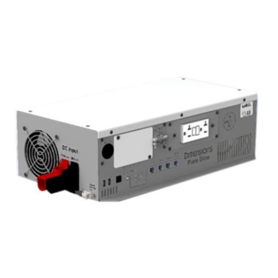
Components Figure 1 Components A. GFCI (not available with “H” suffix) B. Status LED C. Local On/Off D. AC Input and Output Breakers (no AC input breaker for inverter-only models) E. Bonding Lug F. DC Input Connections G. Remote On/Off Wiring Tab H. -
Page 8: Design Features
Design Features • GFCI: Provides 120 VAC output. Only replace with an approved GFCI. • Status LED: This LED will show inverter operation mode and troubleshooting information. See the table in the troubleshooting section at the rear of the manual for further operation mode descriptions. •... -
Page 9: Installation
INSTALLATION Mount Inverter WARNING: Power inverters produce hazardous voltages. To avoid risk of harm or fire, the unit must be properly installed. WARNING: Power inverters should not be mounted in a location that may be exposed to rain or spray. WARNING: Power inverters should not be installed in a zero-clearance enclosure. -
Page 10: Dc Wire Gauge & Fusing
An inverter cable kit (positive cable, negative cable, and proper fuse) is needed to connect the inverter to a battery bank. An inverter cable kit designed to SAE guidelines can be purchased directly from Sensata – call for options. Min. Cable and Max. Fusing Guide for 3% Voltage Drop at 100% Output... - Page 11 DC Wire Gauge & Fusing Continued Make an Inverter Cable Kit 1. Use a stranded copper cables in all cases. NOTE: The recommended maximum length of the inverter cable is 15 ft, and it must be fused within 18 inches of the positive (+) terminal of the battery.
- Page 12 DC Wire Gauge & Fusing Continued Typical Cable Connection Procedure NOTE: Refer to Figure 4 for a typical DC wiring diagram. See Table 2 for proper cable sizes. 1. Remove the fuse from the fuse holder. 2. Connect the inverter’s bonding lug to ground of the vehicle chassis. 3.
-
Page 13: Ac Input/Output Connections
AC Input/Output Connections WARNING: Damage to the power inverter will occur if an external AC power source is applied to the inverter’s AC hardwire output. WARNING: Do not directly connect another source of AC power to the AC output of the inverter. This will result in damage not covered under warranty. - Page 14 AC Input/Output Connections Continued Figure 7 AC Input for Charger/Bypass NOTE: The AC input should be protected by a 20 A branch rated breaker external to the inverter/charger. NOTE: The AC output should be protected by a branch rated breaker external to the inverter if required to comply with the National Electric Code, NFPA 70, or the Canadian Electrical Code, C22.1.
-
Page 15: Bts Connection
BTS Connection Charger operation with a battery temperature sensor, or BTS, cable is required. The BTS measures the battery temperature and automatically adjusts the charger output for the fastest and safest charge. Lead-Acid When batteries are cold, their chemical reaction is slowed, and the battery will not charge as easily in this condition. A charge voltage optimized for room temperature will not charge the battery at low temperatures. - Page 16 BTS Connection Continued Install the BTS 1. Connect the lug end of the battery temperature sensor to the battery. NOTE: Lead-acid battery type will connect the BTS to the negative post of the battery. LFP battery types will connect the BTS to the positive post of the battery. 2.
-
Page 17: Remote Inverter On/Off Switch
Remote Inverter “On/Off ” Switch Remote Inverter “On/Off ” Switch Installation – Customer Supplied For non “-R” suffix versions, a momentary switch must be used. In non-remote only mode, the momentary switch will toggle the inverter state between on and off, or standby and off while in charge mode. The remote switch may be customer supplied or ordered separately from the factory. -
Page 18: Operation
OPERATION Once the inverter has been fully installed, wired, and DC power has been applied, the inverter is ready to turn on. The status LED beneath the AC wiring box on the left side of the inverter shows the current state of the inverter. Inverter Power Mode Usage: Any 120 VAC, 60 Hz single phase product within the inverter’s power rating. -
Page 19: External Power Mode
External Power Mode Battery Charger The status LED located on the side of the inverter will blink green to indicate the charging process mode. See the LED Status Chart for additional blink codes. NOTE: The battery charger requires about 8.5 VDC to be present at the DC output before the charger will operate. The battery charger will engage automatically and independently of the inverter on/off status. - Page 20 External Power Mode Continued Battery Charger Continued Battery Type Bulk Charge Phase Current Limit SEE SPEC 1. When battery voltage reaches the accept voltage Phase Terminates 2. Bulk charge will extend when load management reduces charger current below 50% (25 A) Accept Charge Phase Accept charge voltage 14.3 VDC...
- Page 21 External Power Mode Continued Battery Charger Continued Battery Type Battery Temperature Charger Warm Battery: output switches to >50°C/ 122°F compensated float from bulk/accept/off (hot) <60°C/140°F Charger High Battery Temp: output to off >60°C/140°F See Profile Charger resumes in previous mode: bulk/ Profile value <45°C/112°F accept/float...
- Page 22 External Power Mode Continued Cold Charging (LFP Only) Under normal charger operation, if the battery temperature drops below 5°C/41°F while charging, the charger will switch to 0.1C charging. If the temperature increases to 10°C/50°F, the charger will resume normal charging. If the charger drops to 0°C/32°F, the charger will shut down, and it will restart 0.1C charging at 5°C/41°F.
- Page 23 External Power Mode Continued Equalization Available only for wet lead-acid batteries, this function overcharges the battery in a controlled way to remove sulphate buildup from the battery’s internal plates. Consult your battery manufacturer on how frequently the equalization process should be carried out. Equalization can only be initiated with a RV-C CAN command. The process will not start until a full charge cycle has been completed.
-
Page 24: Gfci
GFCI A GFCI measures the amount of AC current into the GFCI line side “hot” and “neutral” terminals. Both terminals should measure the same amount of current under normal conditions. Any difference in current is considered the leakage current. If the leakage current is greater than 5mA, the GFCI will trip. A tripped GFCI suggests that there has been a breakdown in the electrical insulation of a connected unit. -
Page 25: Configurations
CONFIGURATIONS Non-Volatile Memory (NVM) Setup Utility The inverter/charger settings may be adjusted with a NVM Setup Utility kit which is sold separately. The kit consists of a Kvaser® CAN interface which connects to a USB port on a laptop, a DB9 to RJ45 adapter, a terminating resistor, and a Windows PC program that can be installed on a x32 or x64 machine. -
Page 26: Default Configurations
Configurations Options Increment Default Low Batt 10.0 V 13.0 V .1 V 10.5 V (11.5 V for LFP) 20 A 15 A AC Line Qualify 5 secs 30 secs 5 secs 30 secs CAN Instance Baud Rate 250k 500k 250k Table 6 Setting Options Settings Battery Type... -
Page 27: Switch Options
Switch Options The inverter can be configured by the factory or through the NVM Setup Utility to have different local and remote switch configurations. The local switch may be set to enabled or disabled. The remote switch may be set to snap or momentary. -
Page 28: Shutdown Timer
Shutdown Timer As an alternative to sleep mode, a factory configured shutdown timer is available to disable the inverter after fixed periods (regardless of the output load). Standard timer settings are “off,” 30 minutes, and 60 minutes. Following the shutdown, the DC input current will be less than 0.5mA. Cycling the on/off control will restart the inverter. Auxiliary Control The AUX tab on the side of the inverter allows for additional functionality of the inverter. -
Page 29: Battery Options
Battery Options The charger can be set to charge four different types of batteries: wet lead-acid, AGM, gel, or LFP. The charger is set to AGM by default by the factory. The battery type may be changed at the factory or through the NVM Setup Utility. -
Page 30: Troubleshooting
WARNING: Do not remove chassis cover. No user-serviceable parts inside. Call or e-mail customer service for free consultation during business hours. Business hours are 8:00 am –5:00 pm C.S.T. Phone: 1-800-553-6418 or 1-651-653-7000 E-mail: inverterinfo@sensata.com Fax: 1-888-439-3565 or 1-651-653-7600 Website: http://magnum-dimensions.com/ LED Status Chart –... -
Page 31: Inverter Faults And Warnings
Inverter Faults and Warnings Inverter Status LED Fault States LED Color & State ACC Remote LED Operating Condition State No Power to Unit or Internal Fault Amber — Solid Constant on Low Battery 0–5 Seconds (Warning) Red — Solid Constant on Overload 0–5 Seconds (Warning) Red —... - Page 32 Inverter Faults and Warnings Continued • System Overload/Output Short Circuit: The inverter has detected that the output has short circuited. Alternatively, if the input voltage to the inverter is approaching the low battery setpoint and a heavy load is applied, the output voltage may collapse, causing the inverter to fault like an output short circuit. The inverter power will need to be cycled to restart the inverter.
-
Page 33: Charger Faults And Warnings
Charger Faults and Warnings Charger Status LED Fault States LED Color & State ACC Remote LED State Operating Condition None No Power to Unit or Internal Fault Amber — 1 blink Fast blink Charger Off — Check Battery Probe Amber — 2 blinks Fast blink Charger —... -
Page 34: Troubleshooting Guide
Troubleshooting Guide Problem Possible Causes Check if the in-line fuse which is located within 18” from the battery’s positive post is installed or open. Check if DC connections are tight and clean. Check if the AC output circuit breaker is tripped. Check if the switches are on. -
Page 35: Appendix
APPENDIX Accessories & Replacement Parts Part Number Item Description 430005 GFCI outlet, Leviton GFNT2 431021 Fuse holder with cover 430012 Fuse 350 A, ANN-350 430010 Fuse 200 A, ANN-200 430011 Fuse 250 A, ANN-250 430012 Fuse 300 A, ANN-300 612007 20 ft. -
Page 36: Can
The inverter is compatible with RV-C CAN, developed by the RVIA (Recreational Vehicle Industry Association). CAN allows for the inverter to communicate with other units on the network. For CAN to work properly, the inverter and all other units on the CAN network must be using the same CAN protocol. - Page 37 Setting Notes Low Battery 10.0 V 13.0 V 0.1 V Increments Battery Type Battery Profile Branch Circuit Disabled 20 A Rating 5 A Increments AC Line Qualify 5 Seconds 30 Seconds 5 Sec Increments CAN Instance CAN Baud Rate 250K 500K CV Timeout 0.5 Hrs...
-
Page 38: Limited Warranty Terms & Conditions
Sensata and the manufacturer’s written instructions. Sensata’s sole liability and the Purchaser’s sole remedy for a failure of goods under this limited warranty and for any and all claims arising out of the purchase and use of the goods shall be limited to the repair or replacement of the goods that do not conform to this warranty. - Page 40 4467 White Bear Parkway St. Paul, MN 55110 Phone: 651-653-7000, 800-553-6418 Fax: 651-653-7600, 888-439-3565 inverterinfo@sensata.com http://magnum-dimensions.com/ Document# 122229 Revision A 12LPC15 Manual...
Need help?
Do you have a question about the Dimensions 12LPC15 and is the answer not in the manual?
Questions and answers