
Subscribe to Our Youtube Channel
Related Manuals for Sensata DIMENSIONS 12/1800N


Summary of Contents for Sensata DIMENSIONS 12/1800N
- Page 1 DC to AC Power Inverter Pure Sine Wave Output Owner’s Manual Models: 12/1800N 12/2400N 12/3000N Models: 12/3600N 12/800N 12/1200N 12/1500N...
-
Page 2: Table Of Contents
TABLE OF CONTENTS Introduction ..............................3 Contact Us ...................................3 Important Safety Information ............................4 Specifications ..................................6 Components ..................................7 Design Features ...................................8 Installation ..............................9 Mount the Inverter ................................9 DC Wire Gauge & Fusing ...............................11 Remote Inverter “On/Off ” Switch ..........................17 Operation ..............................18 Inverter Power Mode ...............................18 Troubleshooting ............................ -
Page 3: Introduction
INTRODUCTION Thank you for purchasing a Dimensions™ inverter from Sensata Technologies®! We think that you will find this product to be extremely reliable and easy to use. Please read this manual completely before installing or operating the unit. Contact Us Sensata Technologies can be reached by phone or email if you need assistance with this product. -
Page 4: Important Safety Information
Save this manual and keep it in a safe place. Sensata Technologies is an ISO 9001:2015 Registered Company. Sensata uses the following special notices to help prevent injury and/or damage to equipment: Safety Symbols DANGER indicates an imminently hazardous situation which, if not avoided, will result in death or serious injury. -
Page 5: Battery Safety Instructions
Inverter Safety Instructions WARNING: Power inverters produce hazardous voltages. To avoid risk of harm or fire, the unit must be properly installed. WARNING: There are no user serviceable parts inside. Do not remove the cover. WARNING: Power inverters should not be mounted in a location that may be exposed to rain or spray. WARNING: Power inverters should not be installed in a zero-clearance enclosure. -
Page 6: Specifications
Specifications Models 12/800N 12/1200N 12/1500N 12/1800N 12/2400N 12/3000N 12/3600N Output Power 1200 1500 1800 2400 3000 3600 (Watts Cont.) Output Current Up to 7 Up to 10 Up to 12.5 Up to 15 Up to 20 Up to 25 Up to 30 (Amps AC) Peak Output (Amps DC) -
Page 7: Components
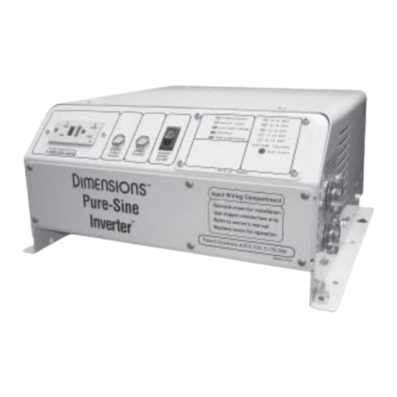
Components Figure 1 A. GFCI B. Status LED C. AC Input Breaker D. Output Breaker E. Local “On/Off ” Switch F. Input Wiring Access Cover G. Bonding Lug Page 7 Manual... -
Page 8: Design Features
Design Features • Unit Protection: Automatic inverter short circuit/overload protection, automatic over temperature shutdown, and AC output circuit breaker. • Battery Protection: Automatic low battery shutdown at 10.5 VDC with an in-rush delay. • Status LED: This LED will show inverter operation mode and troubleshooting information. See the table in the troubleshooting section at the rear of the manual for further operation mode descriptions. -
Page 9: Installation
INSTALLATION Mount Inverter Installation Tools • Wire Termination Crimper • Cable Ties • Drill • #2 Phillips Screw Driver (with a magnetic end) • Slotted Screw Driver • Tape Measure • Wire Cutters • Needle Nose Pliers • Wire strippers Inverter Mounting Recommendations NOTE: The inverter mounting location should provide adequate ventilation and clearance to maintain room temperature during operation. -
Page 10: Dc Wire Gauge & Fusing
An inverter cable kit (a positive cable, negative cable, and proper fuse) is needed to connect the inverter to a battery bank. An inverter cable kit designed to SAE guidelines can be purchased directly from Sensata – call for options. An 8 AWG cable is also required to connect the inverter’s bonding lug to ground. - Page 11 DC Wire Gauge & Fusing Continued Make an Inverter Cable Kit 1. Use a stranded copper cables in all cases. NOTE: The inverter cable length and the size of the inverter will determine the cable gauge and the size fuse to use.
- Page 12 Typical DC Cable Connections for 12/800N, 12/1200N, and 12/1500N Figure 3 Page 12...
- Page 13 Typical DC Cable Connections for 12/1800N, 12/2400N, 12/3000N and 12/3600N Figure 4 Page 13...
- Page 14 Wiring Diagram for 12/800N, 12/1200N, and 12/1500N Figure 5 Page 14 Manual...
- Page 15 Wiring Diagram for 12/1800N, 12/2400N, 12/3000N and 12/3600N Figure 6 Page 15 Manual...
-
Page 16: Remote Inverter "On/Off " Switch
Remote Inverter “On/Off ” Switch Install Remote Inverter “On/Off ” Switch – Customer Supplied An optional remote switch with an integral LED can be purchased and used to control the inverter. Route the cable to the inverter and plug into the connector on the back. 1. -
Page 17: Operation
OPERATION Once the inverter has been fully installed, wired, and DC power has been applied, the inverter is ready to turn on. The status LED beneath the AC wiring box on the left side of the inverter shows the current state of the inverter. Inverter Power Mode Usage: Any 120 VAC, 60 Hz single phase product within the inverter’s power rating. -
Page 18: Troubleshooting
WARNING: Do not remove chassis cover. No user-serviceable parts inside. Call or email customer service for free consultation during business hours (7:30 am - 5:30 pm C.S.T). Phone: 1-800-553-6418 or 1-651-653-7000 E-mail: inverterinfo@sensata.com Fax: 1-888-439-3565 or 1-651-653-7600 Website: http://magnum-dimensions.com/ Figure #... -
Page 19: Troubleshooting Guide
Troubleshooting Guide 1. Plug a 100 watt light bulb into the inverter’s AC outlet. 2. Switch on the remote On/Off switch (if available). 3. Turn the inverter’s local “On/Off ” for 5 seconds before switching it back on. If the work light turns on, the inverter works. -
Page 20: Appendix
APPENDIX Accessories & Replacement Parts Part Number Item Description Fuse 150 A, ANN-150 430010 Fuse 200 A, ANN-200 430011 Fuse 250 A, ANN-250 430012 Fuse 300 A, ANN-300 430054 Fuse 350 A, ANN-350 430019 Fuse 400 A, ANN-400 430020 Fuse 500 A, ANN-500 430067 Fuse 600 A, ANN-600 Table #... - Page 21 Form #122187 Revision C XXXX Manual...
Need help?
Do you have a question about the DIMENSIONS 12/1800N and is the answer not in the manual?
Questions and answers