
Related Manuals for Sensata Dimensions 24NP36


Summary of Contents for Sensata Dimensions 24NP36
- Page 1 DC to AC Power Inverter/Charger 24 VDC to 120 VAC Pure Sine Wave Output Owner’s Manual Models: 24NP36...
-
Page 2: Table Of Contents
TABLE OF CONTENTS Introduction ..............................3 Safety Information ................................4 Specifications ..................................6 Components ..................................7 Design Features ...................................8 Installation ..............................9 Mount the Inverter ................................9 Wiring Diagram .................................10 DC Wire Gauge & Fusing ...............................11 AC Input & Output Connections ..........................12 BTS Connection ................................13 Remote Operation ................................15 NP Control Board Pinout ...............................17 Operation .............................. -
Page 3: Introduction
Please read this manual completely before installing or operating the unit. All information is subject to change without warning. Contact Sensata for the latest updates. Contact Us Sensata Technologies can be reached by phone or email if you need assistance with this product. Phone: 1-800-553-6418 or 1-651-653-7000 E-mail: inverterinfo@sensata.com Fax: 1-888-439-3565 or 1-651-653-7600 Website: http://magnum-dimensions.com/... -
Page 4: Safety Information
Save this manual and keep it in a safe place. Sensata Technologies is an ISO 9001:2015 Registered Company. Sensata uses the following special notices to help prevent injury and/or damage to equipment: Safety Symbols DANGER indicates an imminently hazardous situation which, if not avoided, will result in death or serious injury. - Page 5 Inverter Safety Instructions WARNING: Customer must match battery type with charger battery type. WARNING: Power inverters produce hazardous voltages. To avoid risk of harm or fire, the unit must be properly installed. WARNING: There are no user serviceable parts inside. Do not remove the cover. WARNING: Power inverters should not be mounted in a location that may be exposed to rain, spray, salt, or corrosive chemicals.
-
Page 6: Specifications
Specifications WARNING: The inverter is intended to recharge batteries. The battery that is connected to this product is only suitable if it complies with the given battery standard for that battery type and is provided with a battery management system that will monitor and control the electrical and thermal health of the battery during charging. -
Page 7: Components
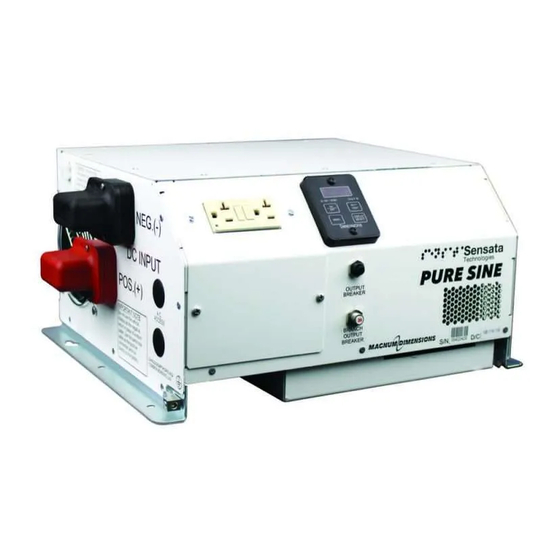
Components Figure 1 Components A. DC Input B. Bonding Lug C. AC Input & Output (Hardwired) D. AUX Connector E. Remote Switch Wiring Tab F. Status LED G. 7-Segment Display H. GFCI I. AC Wiring Plate J. 20 A GFCI Output Breaker K. -
Page 8: Design Features
Design Features • DC Input: Connects to the 24 VDC battery bank. • Bonding lug: Connects to the system ground. • AC Input & Output (Hardwired): Terminal blocks are provided behind front access cover for hardwiring AC Input and Output. A second set of openings to access the AC terminals can be found on the underside of the inverter/charger when using the large chassis. -
Page 9: Installation
INSTALLATION Mount the Inverter NOTE: The inverter mounting location should provide adequate ventilation and clearance to maintain room temperature during operation. At least ½” of clearance is required on all sides except the bottom. This includes ½” beyond the mounting flanges and DC terminal covers. Installation Tools The following tools may be required for inverter installation: •... -
Page 10: Wiring Diagram
Typical Wiring Diagram 15 ft. Max Black Neg (-) 15 ft. Max Red Pos (+) To Chassis Ground LFP to Battery Fuse 18 in. Max Red Pos (+) Bank Pos (+) 24 VDC Battery Lead-Acid to Battery Bank Neg (-) Figure 3 Typical Wiring Diagram 1. -
Page 11: Dc Wire Gauge & Fusing
DC Wire Gauge & Fusing An “Inverter Cable Kit” (positive cable, negative cable, and proper fuse) is needed to connect the inverter to a battery bank. An 8 AWG single-strand cable is also recommended to connect the inverter’s bonding lug to ground. The inverter cable length and the size of the inverter will determine the cable gauge and the fuse size to use. -
Page 12: Ac Input & Output Connections
AC Input & Output Connections WARNING: Do not connect another source of AC power directly to the output of the inverter. This will result in damage not covered under warranty. WARNING: Do not reverse the input and output AC connections. This will result in damage not covered under warranty. -
Page 13: Bts Connection
BTS Connection Charger operation with a battery temperature sensor, or BTS, cable is required. The BTS measures the battery temperature and automatically adjusts the charger output for the fastest and safest charge. Lead-Acid When batteries are cold, their chemical reaction is slowed, and the battery will not charge as easily in this condition. A charge voltage optimized for room temperature will not charge the battery at low temperatures. - Page 14 BTS Connection Continued Install the BTS 1. Connect the lug end of the battery temperature sensor to the battery. NOTE: Lead-acid battery type will connect the BTS to the negative post of the battery. LFP battery types will connect the BTS to the positive post of the battery. 2.
-
Page 15: Remote Operation
Remote Operation Install 7-Segment Display Panel The 7-segment display panel can be removed from the inverter and installed in a different location in the vehicle for remote control and monitoring. 1. Unscrew the two screws that hold the panel in using a 3/32” Allen wrench. 2. - Page 16 Remote Operation Continued Remote Inverter “On/Off ” Switch An optional customer-supplied remote switch can also be used to control the inverter. Install Remote Inverter “On/Off ” Switch 1. Using an insulated female faston and 18 AWG wire, wire between the “Remote On/Off ” connection on the right side of the inverter and the remote switch.
-
Page 17: Np Control Board Pinout
NP Control Board Pinout An additional switch may be installed as an optional way to enable the inverter. Enable remote operation by installing a switch between between the pin 4 and 6. The installed switch must be rated for 80 V minimum. ACC Jack 1 2 3 4 5 6 CAN H... -
Page 18: Operation
OPERATION Inverter Power Mode Control the inverter with the display panel “On/Off ” key or a voltage between 8 and 32 volts applied to the “Remote On/Off ” input tab. The 7-segment display panel “On/STBY” LED will be green, and the status LED will blink amber while the inverter is on. - Page 19 External Power Mode Continued Battery Charger Continued Battery Type Bulk Charge Phase Current Limit SEE SPEC 1. When battery voltage reaches the accept voltage Phase Terminates 2. When the bulk charge timeout is reached 6 Hours Phase Timeout Bulk charge timers will extend when load management reduces charger current below 50% (25 A) Accept Charge Phase Accept charge voltage...
- Page 20 External Power Mode Continued Battery Charger Continued Battery Type Battery Temperature Charger Warm Battery: output switches to >50°C/ 122°F compensated float from bulk/accept/off (hot) <60°C/140°F Charger High Battery Temp: output to off >60°C/140°F See Profile Charger resumes in previous mode: bulk/ Profile value <45°C/112°F accept/float...
- Page 21 External Power Mode Continued Cold Charging (LFP Only) Under normal charger operation, if the battery temperature drops below 5°C/41°F while charging, the charger will switch to 0.1C charging. If the temperature increases to 10°C/50°F, the charger will resume normal charging. If the charger drops to 0°C/32°F, the charger will shut down, and it will restart 0.1C charging at 5°C/41°F.
-
Page 22: Operation Using 7-Segment Display
Operation Using 7-Seg Display Once the inverter has been fully installed, wired, and DC power has been applied, the 7-Segment (“7-Seg”) display panel will power on. This display panel shows the status and configuration information of the inverter and charger. The inverter can be turned on and off by pressing the “On/Off ”... - Page 23 Operation Using 7-Seg Display Continued Inverter Power Mode (Using 7-Seg Display Panel) Turning the Inverter On or Off (No AC Applied) Press the “On/Off ” key to turn on the inverter. The “On/STBY” LED will turn green. Press the “On/Off ” key again to turn the inverter off.
- Page 24 Operation Using 7-Seg Display Continued Inverter Power Mode (Using 7-Seg Display Panel) Continued Battery Test The battery voltage can be tested at any time by pressing the “Batt Test” key. The mode will stay active for 1 minute or until the “Batt Test” or “Menu” key is pressed. Battery Minimum (Low Battery Voltage Point) If the inverter temporarily shuts down while in use due to a low DC input condition, it is possible to check how low the DC input voltage was measured.
- Page 25 Operation Using 7-Seg Display Continued External Power Mode (Using 7-Seg Display Panel) AC Input Limit (BCR max limit) The maximum AC current that the charger will be allowed to draw is adjustable. The default setting is 15 A. Press “Menu” to display the current setting. The message will then scroll: AC In LNt 15A To change the value press “Display/Select”...
-
Page 26: Operation Using Remote On/Off Switch
Operation Using Remote “On/Off ” Switch The inverter is ready to turn on once the inverter and remote “On/Off ” switch has been fully installed, wired, and DC power has been applied. The status LED on the right side of the inverter shows the status information of the inverter and charger. -
Page 27: Gfci Operation
GFCI Operation A GFCI measures the amount of AC current into the GFCI line side “hot” and “neutral” terminals. Both terminals should measure the same amount of current under normal conditions. Any difference in current is considered the leakage current. If the leakage current is greater than 5mA, the GFCI will trip. A tripped GFCI suggests that there has been a breakdown in the electrical insulation of a connected device. -
Page 28: Optional Lcd Remote
Operation with Optional LCD Remote LCD Remote A LCD remote may be purchased separately for “R” suffix models to connect to the inverter through the RJ45 port on the front of the inverter. The remote display will provide the current input voltage and output wattage of the inverter while in inverter mode. -
Page 29: Configurations
CONFIGURATIONS Setting Configuration with Non-Volatile Memory (NVM) Setup Utility The inverter/charger settings may be adjusted with a NVM Setup Utility kit which is sold separately. See the Appendix for the part number of the kit. The kit consists of a Kvaser® CAN interface which connects to a USB port on a laptop, a DB9 to RJ45 adapter, a terminating resistor, and a Windows PC program that can be installed on a x32 or x64 machine. -
Page 30: Configurations
Configurations Options Increment Default Low Batt 21.0 V 24.0 V .1 V 21.0 V (23.0 V for LFP) 30 A 15 A AC Line Qualify 5 secs 30 secs 5 secs 30 secs CAN Instance Baud Rate 250k 500k 250k Table 8 Setting Options Settings Battery Type... - Page 31 Configurations Continued Battery Options The charger can be set to charge four different types of batteries: wet lead-acid, AGM, gel, or LFP. The charger is set to AGM by default by the factory. The battery type may be changed at the factory or through the NVM Setup Utility.
-
Page 32: Ignition Switch Control With The 7-Seg Display Panel
Ignition Switch Control with the 7-Seg Display Panel The 7-Seg Display Panel can be wired to the vehicle ignition circuitry to control operation of the inverter. When the ignition is turned on, the inverter has a built-in delay which will turn it on after 10 seconds. For the inverter to work in this way, the 7-Seg Display Panel must be programmed for this type of operation. -
Page 33: Branch Circuit Rating (Bcr) Max Limit With The 7-Seg Display Panel
Branch Circuit Rating (BCR) Max Limit with the 7-Seg Display Panel The BCR max limit sets the max limit that is adjustable by the 7-Seg Display. For example, if the limit is set to 15 A, the user may only select 0, 5, 10, or 15 amps. If the limit is set to 30 A, the user may then select from 0–30 amps in 5 A increments. -
Page 34: Troubleshooting
WARNING: Do not remove chassis cover. No user-serviceable parts inside. Call or e-mail customer service for free consultation during business hours. Business hours are 8:00 am –5:00 pm C.S.T. Phone: 1-800-553-6418 or 1-651-653-7000 E-mail: inverterinfo@sensata.com Fax: 1-888-439-3565 or 1-651-653-7600 Website: http://magnum-dimensions.com/... - Page 35 7-Seg Display Panel Messages Continued Condition Display LEDs Action Required Charger Off Amber “On/STBY” chGr OFF bAtt LOW tEMP Battery Low Raise battery temperature. Red “Fault” Temp (LFP Only) Charger Off Check DC wiring for a short or DC Red “Fault” chGr OFF OL Overload load issue.
- Page 36 7-Seg Display Panel Messages Continued Inverter Off Low Battery The inverter is off due to a low battery voltage condition (≤21.0 volts for 5 seconds). Inverter Off Overload The inverter is off due to an overload condition or output short circuit. NOTE: If the inverter/charger has been disabled by CAN, the “Inverter Off Overload”...
- Page 37 7-Seg Display Panel Messages Continued Charger Off Low Battery The charger is off due to low voltage unable to support safe charge. Charger Off Battery Short The charger is off due to a battery short. Page 37 24NP Manual...
-
Page 38: Led Status Chart
LED Status Chart Status LED Normal States LED Color LED State Operating Conditions Green 1 blink Bulk Charge Green 2 blinks Accept Charge Green 3 blinks Float Charge Green 4 blinks Load Management Active Green 5 blinks Equalization Green 6 blinks .Cold Charging Amber 1 blink... - Page 39 LED Status Chart Continued Battery Type LED States at Start-Up (5 Minutes) LED Color Battery Type Amber - Green Wet Lead-Acid Amber - Green - Green Amber - Green - Green - Green Amber - Green (x4) Amber - Green (x5) Custom Battery Type* Amber - Green (x6) Error, Undefined Battery Type...
-
Page 40: Troubleshooting Guide
Troubleshooting Guide Check the in-line fuse which is located within 18 inches from the battery’s positive (+) post Check if DC connections are tight and clean No LED’s On Check if battery voltage is above 21.0 VDC Check remote power switch No AC output Check if GFCI is tripped Disconnect all loads and... -
Page 41: Appendix
Accessories & Replacement Parts Part Number Item Description 215018 Box Lug, 300MCM– 6AWG Type B/C, 4/0 – 6 AWG Type G-K CU9AL UL/CSA 250031 AC cover plate #8-32 x 3/8” Phillips screw 250369-1 DC connector internal tooth 3/8” washer 250430 DC connector brass 3/8”... -
Page 42: System Default Settings
System Default Settings Inverters as shipped from the factory default to the settings in Table 12. Setting Default Value Low Battery 21.0 VDC Branch Circuit Rating 15 A Battery Type Table 16 System Default Settings The battery type and low battery setting may be changed by CAN, 7-Seg Display, or the optional LCD remote. Only the branch circuit rating can be changed with the 7-Seg display. -
Page 43: Can
The inverter is compatible with RV-C CAN, developed by the RVIA (Recreational Vehicle Industry Association). CAN allows for the inverter to communicate with other units on the network. For CAN to work properly, the inverter and all other units on the CAN network must be using the same CAN protocol. - Page 44 CAN Continued Status DGN Number Charger Configuration Status 1FFC6h Charger Configuration Status 2 1FF96h Charger Configuration Status 3 1FECCh Charger Configuration Status 4 1FEBFh Charger Equalization Status 1FF99h Charger Status 1FFC7h Charger Status 2 1FEA3h Charger AC Status 1 1FFCAh Charger AC Status 2 1FFC9h Charger AC Status 3...
-
Page 45: Limited Warranty Terms & Conditions
Sensata and the manufacturer’s written instructions. Sensata’s sole liability and the Purchaser’s sole remedy for a failure of goods under this limited warranty and for any and all claims arising out of the purchase and use of the goods shall be limited to the repair or replacement of the goods that do not conform to this warranty. - Page 46 Setting Notes Low Battery 21.0 V 24.0 V 0.1 V Increments Battery Type Battery Profile Branch Circuit Disabled 30 A Rating 5 A Increments AC Line Qualify 5 Seconds 30 Seconds 5 Sec Increments CAN Instance CAN Baud Rate 250K 500K CV Timeout 0.5 Hrs...
- Page 48 4467 White Bear Parkway St. Paul, MN 55110 Phone: 651-653-7000, 800-553-6418 Fax: 651-653-7600, 888-439-3565 inverterinfo@sensata.com http://magnum-dimensions.com/ Document# 122214 Revision C 24NP Manual...
Need help?
Do you have a question about the Dimensions 24NP36 and is the answer not in the manual?
Questions and answers