Table of Contents
Advertisement
Quick Links
Advertisement
Table of Contents

Related Manuals for Sensata SSI-12HF3.5N


Summary of Contents for Sensata SSI-12HF3.5N
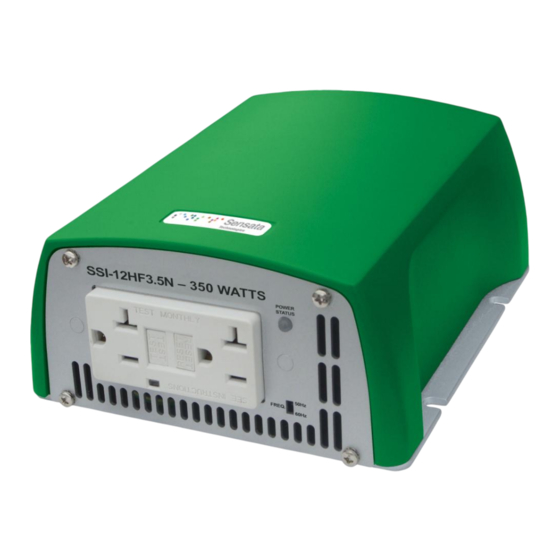
- Page 1 SSI-12HF3.5N Owner’s Manual Form 122185...
-
Page 2: Table Of Contents
4. Installations ............10 4-1 General Installation Recommendations....10 4-2 DC Wiring Connections ........11 4-3 Wiring Diagram ..........12 4-4 AC Safety Grounding ........13 4-5 Inverter Operation ........... 13 Troubleshooting Guide ........... 14 Maintenance ............15 Warranty ..............15 http://dimensions.sensata.com... -
Page 3: Important Safety Information
1-2-4. Remove personal metal items such as rings, bracelets, necklaces, and watches when operating with lead-acid batteries. Failure to do so may result in a spark or short circuit event, which can result in very high temperatures that can melt the metal items and potentially cause serious bodily harm. http://dimensions.sensata.com Page 3... -
Page 4: Introduction
Automatic low battery shutdown at 10.5 VDC (with in-rush delay) Approvals: FCC Class A approved. Nomenclature Three letter suffix designation Base model 12 - Pure sine signal output Wattage output: 3.5 = 350 HF: High frequency inverter Input voltage: 12 = 12VDC SSI: Sensata Series Inverters http://dimensions.sensata.com Page 4... -
Page 5: Specifications
SSI Series Owners Manual Specifications Specification Model No. Item SSI-12HF3.5N Continuous Output Power (Watts) Maximum Output Power (Watts) Surge Rating (Max) (Watts) Input voltage (VDC) Input Current (Amps DC) 100 / 110 / 120Vac +/- 5% Output Voltage (VAC) Frequency (Switch Selectable) 50 / 60Hz +/- 0.05%... -
Page 6: Locating Controls And Ports
3. Locating Controls and Ports 3-1. Front View Ventilation Openings: Allows airflow passing to cool down the inside electronics. AC frequency switch settings Output Frequency Dip Switch 50 Hz 60 Hz NOTE: Default frequency setting is 60Hz for USA usage. http://dimensions.sensata.com Page 6... -
Page 7: Rear Panel Operation
Intermittent Blink – – – – – – Over Temperate Protection Solid ———————— Over Load Protection GFCI Outlet: AC output power 3-2 Rear View Chassis Ground: Use wire # 8 AWG to connect Chassis ground with vehicle chassis. http://dimensions.sensata.com Page 7... -
Page 8: Protection Features
Over Temperature Protection Under Over Voltage Under INTERIOR Model Voltage Voltage Shut- Shut- Alarm Shut-down Restart Restart Restart down down 12 V 11.0V <10.5V 12.5 55° C 45° C Note: The specifications are subject to change without notice. http://dimensions.sensata.com Page 8... -
Page 9: Remote Panel .Connection
3-4-1-4. Remote Port: Place 0.75mm and Screw type cable between the remote port and the panel. 3-4-1-5. Remote port ON/OFF inverter setup status MODE Ⅰ MODE Ⅳ NOTE: Only one of control mode can be presented. When operating. http://dimensions.sensata.com Page 9... -
Page 10: Installations
Shock hazard; before proceeding further, carefully check that the inverter is NOT connected to any batteries, and that all wiring is disconnected from any electrical sources. Do not connect the output terminals of the inverter to an incoming AC source. http://dimensions.sensata.com Page 10... -
Page 11: Dc Wiring Connections
POS. [ + ] and black terminal represents negative NEG. [ – ]. Insert the cables into the terminals and tighten the screw to clamp the wires securely. Sensata Technologies recommends using only high quality (SGX) insulated copper wire and keep the cable length short, a maximum of 3 to 6 feet. -
Page 12: Wiring Diagram
ON: INV - ON EVT PWR OFF: INV - OFF GND START MODE +12V START MODE Rear View POWER DC INPUT REMOTE REMOTE PORT CHASSIS GROUND 10.5-15.0VDC FUSE Optional: Cable assembly with 50Amp fuse (P/N: 650350-10) 12 Volts http://dimensions.sensata.com Page 12... -
Page 13: Ac Safety Grounding
If you plan to accurately measure the true output R.M.S. voltage of the inverter, a meter such as FLUKE 87 or better, or any Multi-Meter marked as ―True RMS‖ must be used. http://dimensions.sensata.com Page 13... -
Page 14: Troubleshooting Guide
RED, blinking intermittently Over Temperature (OTP) Improve ventilation, make sure inverter vents are not obstructed, lower ambient temperature d. RED, solid ON Short circuit, overload or wiring Check AC wiring for short circuit, error (OLP) reduce the load http://dimensions.sensata.com Page 14... -
Page 15: Maintenance
Please note that Sensata Technologies is only responsible for ensuring our products are operational before delivering. This warranty will be considered void if the unit has been misused, altered, or accidentally damaged. Sensata Technologies is not liable for anything that occurs as a result of the user’s fault. http://dimensions.sensata.com... - Page 16 SSI Series Owners Manual http://dimensions.sensata.com Page 16...
- Page 17 Sensata assumes no responsibility for infringement of patents or rights of others based on Sensata applications assistance or product specifications since Sensata does not possess full access concerning the use or application of customers’...
Need help?
Do you have a question about the SSI-12HF3.5N and is the answer not in the manual?
Questions and answers