KERN ALJ Operating Manual
Analytical and precision balances
Hide thumbs
Also See for ALJ:
- Operating instruction (304 pages) ,
- Operating manual (78 pages) ,
- Operating instructions manual (260 pages)
Table of Contents
Advertisement
Operating manual
Analytical and precision balances
KERN ALJ/ALS/PLJ/PLS
Type TALJG-A / TALSG-A / TPLJG-A / TPLSG-A
Version 1.1
2020-12
GB
KERN & Sohn GmbH
Ziegelei 1
D-72336 Balingen
E-mail: info@kern-sohn.com
TALJG_A/TALSG_A/TPLJG_A/TPLSG_A-BA-e-2011
Phone: +49-[0]7433-9933-0
Fax: +49-[0]7433-9933-149
www.kern-sohn.com
Advertisement
Table of Contents

Related Manuals for KERN ALJ


Summary of Contents for KERN ALJ
- Page 1 KERN & Sohn GmbH Ziegelei 1 Phone: +49-[0]7433-9933-0 D-72336 Balingen Fax: +49-[0]7433-9933-149 E-mail: info@kern-sohn.com www.kern-sohn.com Operating manual Analytical and precision balances KERN ALJ/ALS/PLJ/PLS Type TALJG-A / TALSG-A / TPLJG-A / TPLSG-A Version 1.1 2020-12 TALJG_A/TALSG_A/TPLJG_A/TPLSG_A-BA-e-2011...
-
Page 2: Table Of Contents
ALJ/ALS/PLJ/PLS KERN Version 1.1 2020-12 Operating manual Analytical and precision balances Contents Technical specification ................. 5 Declaration of Conformity ................15 Device overview ................... 16 Parts .........................16 Operating controls ....................20 3.2.1 Keyboard overview ........................20 3.2.2 Navigation buttons / Introducing the numerical value .............. 21 Display overview .......................22... - Page 3 Basic mode ....................42 Switching the scale on and off ..................42 Resetting ........................42 Ordinary weighing .....................43 Weighing range indicator ..................43 Taring ........................44 Weighing using the under-scales weighing hanger ...........45 Setup menu ....................46 11.1 Weight units (unit1/unit2) ..................49 11.2 RS-232 ........................50 11.3 Transmission speed ....................51 11.4...
- Page 4 15.1 Cleaning ........................95 15.2 Maintenance and service ..................95 15.3 Disposal ........................96 Help for any minor failures ................. 96 Ionizing unit (factory option for KERN ALJ-A03) ........97 17.1 General information ....................97 17.2 Basic safety instructions ...................97 17.3 Technical specification ....................99 17.4...
-
Page 5: Technical Specification
1 Technical specification KERN ALJ 160-4A ALJ 200-5DA Product number / type TALJG 160-4-A TALJG 220-5-A Weighing range (Max) 160 g 82 g/220 g Interval (d) 0.1 mg 0.01 mg/0.1 mg Reproducibility 0.1 mg 0.04 mg/0.1 mg Linearity ±0.3 mg ±0.1 mg/0.2 mg... - Page 6 KERN ALJ 250-4A ALJ 310-4A ALJ 500-4A Product number / type TALJG 250-4-A TALJG 310-4-A TALJG 510-4-A Weighing range (Max) 250 g 310 g 510 g Interval (d) 0.1 mg 0.1 mg 0.1 mg Reproducibility 0.1 mg 0.1 mg 0.2 mg Linearity ±0.3 mg...
- Page 7 KERN ALJ 160-4AM ALJ 250-4AM Product number / type TALJG 160-4M-A TALJG 250-4M-A Weighing range (Max) 160 g 250 g Interval (d) 0.1 mg 0.1 mg Reproducibility 0.1 mg 0.1 mg Linearity ±0.3 mg ±0,3 mg Verification scale interval (e)
- Page 8 KERN ALS 160-4A ALS 250-4A Product number / type TALSG 160-4-A TALSG 250-4-A Weighing range (Max) 160 g 250 g Interval (d) 0.1 mg 0.1 mg Reproducibility 0.1 mg 0.1 mg Linearity ±0.3 mg ±0,3 mg Settling time (standard) Minimum part weight when counting...
- Page 9 KERN PLJ 420-3F PLJ 720-3A PLJ 1200-3A Product number / type TPLJG 420-3-A TPLJG 720-3-A TPLJG 1200-3-A Weighing range (Max) 420 g 720 g 1200 g Interval (d) 0.001 g 0.001 g 0.001 g Reproducibility 0.001 g 0.001 g 0.001 g Linearity ±0.003 g...
- Page 10 KERN PLJ 2000-3A PLJ 4200-2F PLJ 6200-2A Product number / type TPLJG 2100-3-A TPLJG 4200-2-A TPLJG 6200-2-A Weighing range (Max) 2100 g 4200 g 6200 g Interval (d) 0.001 g 0.01 g 0.01 g Reproducibility 0.002 g 0.02 g 0.01 g Linearity ±0.004 g...
- Page 11 KERN PLJ 720-3AM PLJ 6200-2AM Product number / type TPLJG 720-3M-A TPLJG 6200-2M-A Weighing range (Max) 720 g 6200 g Interval (d) 0.001 g 0.01 g Reproducibility 0.001 g 0.01 g Linearity ±0.002 g ±0,02 g Verification scale interval (e)
- Page 12 KERN PLS 420-3F PLS 720-3A PLS 1200-3A Product number / type TPLSG 420-3-A TPLSG 720-3-A TPLSG 1200-3-A Weighing range (Max) 420 g 720 g 1200 g Interval (d) 0.001 g 0.001 g 0.001 g Reproducibility 0.001 g 0.001 g 0.001 g Linearity ±0.004 g...
- Page 13 KERN PLS 4200-2F PLS 6200-2A Product number / type TPLSG 4200-2-A TPLSG 6200-2-A Weighing range (Max) 4200 g 6200 g Interval (d) 0.01 g 0.01 g Reproducibility 0.01 g 0.01 g Linearity ±0.04 g ±0,03 g Settling time (standard) Minimum part weight when...
- Page 14 PLS 20000-1F KERN PLS 8000-2A Product number / type TPLSG 8200-2-A TPLSG 20000-1-A Weighing range (Max) 8200 g 20 kg Interval (d) 0.01 g 0.1 g Reproducibility 0.01 g 0.1 g Linearity ±0.04 g ±0,4 g Settling time (standard) Minimum part weight when...
-
Page 15: Declaration Of Conformity
There is diversification of the counted pieces’ weight 2 Declaration of Conformity The valid Declaration of Conformity EC/UE is available at: www.kern-sohn.com/ce For verified scales (= the ones subject to the conformity assessment procedure), the Declaration of Conformity is included in the delivery scope. -
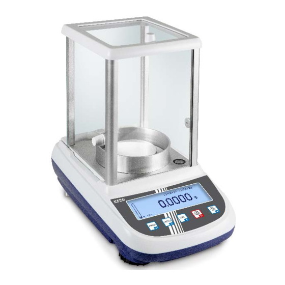
Page 16: Device Overview
3 Device overview 3.1 Parts Front: Model ALJ 200-5DA Models ALJ/ALS Item Name Glass wind breaker Wind breaker ring Scale plate Leveler Display Keyboard Leveling screw foot TALJG_A/TALSG_A/TPLJG_A/TPLSG_A-BA-e-2011... - Page 17 Models PLJ/PLS: Model PLJ 2000-3A Scale plate dimensions Ø 110 mm Item Name Item Name Glass wind breaker Leveler Scale plate Cover of the glass wind breaker Display Glass wind breaker Keyboard Scale plate Leveling screw foot Display Leveler Leveling screw foot Keyboard TALJG_A/TALSG_A/TPLJG_A/TPLSG_A-BA-e-2011...
- Page 18 Models PLS Models PLS 20000-1F scale plate dimensions Ø 160 mm scale plate dimensions 200 x 175 mm Item Name Leveler Scale plate Display Keyboard Leveling screw foot Sample drawing with a ionizing unit installed (KERN ALJ-A03): TALJG_A/TALSG_A/TPLJG_A/TPLSG_A-BA-e-2011...
- Page 19 Scale back and bottom 1. Scale plate 2. RS-232C interface 3. Leveling screw foot 4. Power supply socket 5. Housing screws (in models with 4 leveling screw feet, first screw out both rear ones) 6. Equipment for the under-scales weighing hanger 7.
-
Page 20: Operating Controls
3.2 Operating controls 3.2.1 Keyboard overview Button Name Button pressing Pressing and holding the button until the sound is heard • Displaying the main / • Displaying the setup MENU application menu menu button • Menu item selection — • Leaving the setup scrolling forward menu •... -
Page 21: Navigation Buttons / Introducing The Numerical Value
3.2.2 Navigation buttons / Introducing the numerical value Button Name Button pressing Pressing and holding the button • Increasing the digit value Navigation • In the menu: scrolling Setting a decimal point button forward • Decreasing the digit value Navigation Changing to •... -
Page 22: Display Overview
3.3 Display overview Item Name Weighing range indicator Stabilization indicator Zero indicator Weighing value Unit Current time Current date Symbol Description see chapter Stabilization indicator chapter Zero indicator chapter The scale is in the percentage value determination mode 12.5 chapter The scale is in the piece count mode 12.1 chapter... -
Page 23: User Interface
3.4 User interface Once the application is downloaded, the operator is guided step by step. It is possible to select a language (D, GB, F, IT, ESP, P; see chapter 11.11). Display example “Piece count” Item Name Active application Current date Current time Operation carried out TALJG_A/TALSG_A/TPLJG_A/TPLSG_A-BA-e-2011... -
Page 24: Basic Instructions
KERN (www.kern-sohn.com). The reference weights and scales can be calibrated fast and for a low cost in the KERN calibration laboratory (against the national reference) approved by DKD (Deutsche Kalibrierdienst). -
Page 25: Basic Safety Instructions
5.1 Compliance with the instructions included in the user manual Before you set and start the device, read this user manual thoroughly even if you are familiar with KERN scales. All language versions contain non-binding translation. Only the original document in German is binding. - Page 26 Reinstall any transport locks, if present. Protect all the parts, e.g. glass wind breaker, scale plates, power supply etc. from slipping and damage. TALJG_A/TALSG_A/TPLJG_A/TPLSG_A-BA-e-2011...
- Page 27 Sample drawing for analytical scales: TALJG_A/TALSG_A/TPLJG_A/TPLSG_A-BA-e-2011...
-
Page 28: Unpacking, Positioning And Start-Up
7 Unpacking, positioning and start-up 7.1 Installation place, operation place The scales are designed to ensure reliable weighing results in standard operating conditions. The choice of a correct scale location ensures its accurate and fast operation. This is why you should follow the following rules in the location site: •... -
Page 29: Unpacking And Check
7.2 Unpacking and check Remove the device and accessories from the packaging, remove the packaging material and place the device in the target location. Check if all components included in the delivery are present and not damaged. Scope of delivery / standard accessories •... - Page 30 Scale installation Model ALJ 200-5DA Place the scale plate with the grate. Install the wind breaker ring. Models ALS/ALJ, d = 0.1 mg TALJG_A/TALSG_A/TPLJG_A/TPLSG_A-BA-e-2011...
- Page 31 Models PLS/PLJ, d = 1 mg Models PLS/PLJ, d = 100 mg Models PLS/PLJ, d = 10 mg TALJG_A/TALSG_A/TPLJG_A/TPLSG_A-BA-e-2011...
- Page 32 Leveling Accurate setting and stable installation are the conditions enabling to obtain repeatable results. Small unevenness or inclination of the base surface can be compensated by leveling the scale. • Level the scale using the leveling feet. The air bubble in the leveler must be present in the marked area.
-
Page 33: Power Supply
Check if the scale voltage is set correctly. The scale can be connected to the mains only when the voltage specified on the scale (sticker) and the local voltage are identical. Always use the original power supply by KERN. Using any other products requires KERN consent. Important information: ... -
Page 34: Operator Language Selection
Before you connect or disconnect any extra devices (printer, computer) to/from the data interface, the scale should always be disconnected from the mains. Use solely accessories and peripherals supplied by KERN with the scale, being perfectly compatible with it. 8 Adjustment... -
Page 35: Adjustment Mode Selection
8.1 Adjustment mode selection In the weighing mode press and hold the MENU button until the sound signal stops. The configuration menu is displayed. Using the navigation buttons , select the menu item <Calibration mode>. Confirm by pressing the PRINT button, the current setting will be displayed. -
Page 36: Automatic Adjustment Using The Internal Weight
8.2 Automatic adjustment using the internal weight Factory setting in the models in the verifiable setting (ALJ/PLJ) The automatic adjustment using the internal weight is started automatically: • when the scale was disconnected from the mains, • after the ON/OFF button is pressed in the stand-by mode, •... -
Page 37: Adjustment Using The Internal Weight After The Model Cal Button Is Pressed
8.3 Adjustment using the internal weight after the Model CAL button is pressed (models ALJ/PLJ) Preliminary condition: Menu setting “Internal adjustment”, see chapter 8.1. In the weighing mode, press the CAL button, the adjustment will be carried out automatically. -
Page 38: Adjustment Using The External Weight
8.4 Adjustment using the external weight • Factory setting in ALS/PLS models • In ALJ/PLJ models it is available only in the verifiable setting. • Preliminary condition: Menu setting “External adjustment”, chapter 8.1. • The weight of the recommended adjustment weight, see chapter 1 “Technical Specification”. -
Page 39: Changing The Weight Of The Internal Calibration Weight
8.5 Changing the weight of the internal calibration weight This change can be carried out solely by a specialist holding thorough knowledge of handling scales. Information on reference weights can be found on the Internet at http://www.kern-sohn.com. Display the menu item “Technical adjustment”, see chapter 8.1. ... -
Page 40: Adjustment Report Display/Print
Confirm, pressing the PRINT button. The following will be displayed: date, time, adjustment type and deviation when compared to the most recent adjustment. After the optional printer is connected, the data can be printed by pressing the PRINT button. Sample printout (KERN YKB-01N): 27-08-20 10:41:17 Current date/time Balance ID:... -
Page 41: Verification
8.7 Verification General information: According to the Directive 2014/31/EU, the scales must be verified if they are used in the following way (legally determined scope): a) for commercial purposes when the goods’ price is determined by weighing them, b) to produce medications in pharmacies and also for analyses in medical and pharmaceutical laboratories, c) for official purposes, d) for manufacturing finished packagings. -
Page 42: Basic Mode
9 Basic mode 9.1 Switching the scale on and off Switching on: In the stand-by mode, press the ON/OFF button. The scale is ready to weigh immediately after the weight symbol is displayed. Switching off: Press the ON/OFF button. The scale will be switched to the stand-by mode (energy saving function). -
Page 43: Ordinary Weighing
Wait until the stabilization indicator is displayed [ ]. Read out the weighing result. Once the optional printer is connected, the weighing value can be printed. Sample printouts (KERN YKB-01N): 27-08-20 10:41:17 AM Current date/time Gewic.: 50.5773 g Weighing value 9.4 Weighing range indicator... -
Page 44: Taring
9.5 Taring The empty weight of any container used for weighing can be tared, pressing the button which results in displaying the net weight of the weighed material during consecutive weighing processes. Place the scale container on the scales plate. ... -
Page 45: Weighing Using The Under-Scales Weighing Hanger
9.6 Weighing using the under-scales weighing hanger Weighing using the under-scales weighing hanger enables to weigh any objects which cannot be placed on the scale plate because of their size or shape. Carry out the following steps: • Switch the scale off. •... -
Page 46: Setup Menu
11 Setup menu In the configuration menu, all the basic settings and parameters affecting the total scale operation are entered. Menu navigation Entering the menu In the weighing mode press and hold the MENU button until the sound signal stops. The configuration menu is displayed. - Page 47 Menu overview: Menu item Selection Description Unit 1 gram Unit 2 karat ounce see chapter 11.1) pound Pennyweight Ounce Troy Grain tl 1 Tael (Hong Kong) tl 2 Tael (Singapore) tl 3 Tael (Taiwan) Momme RS-232 Continuous Continuous data transfer see chapter 11.2) Sending the stable weighing value after the PRINT button...
- Page 48 Display contrast 1-15 Contrast selection (see chapter 11.7) Display backlight Backlight on (see chapter 11.8) Backlight off Automatic switch-off of the backlight 3 s after the stable weighing value is achieved. The Auto backlight will be switched on again automatically after the weight is changed or the button is pressed.
-
Page 49: Weight Units (Unit1/Unit2)
11.1 Weight units (unit1/unit2) Weight units which are to be available during operation can be specified in the menu. After different units (unit1 and unit2) are selected, the weighing result can be displayed in two weight units (unit1 and unit2) simultaneously. To switch between the values in weight “unit1”... - Page 50 Unit switching: In the weighing mode press and hold the PRINT button until the sound signal stops, then release the button. Unit 1 Unit 2 • When switching on from the stand-by mode using the ON/OFF button, the scale will be started with the unit used most recently. •...
-
Page 51: Transmission Speed
Symbol Description <Continuous> Continuous data transfer Sending the stable weighing value after the <On demand> PRINT button is pressed Sending data standard printer <Generic printer> following the remote control request. Sending data to the printer supporting the <Printer TLP> LP-50 protocol. setting used obtain... -
Page 52: Auto Zero
11.4 Auto zero This menu item enables to switch on or off the automatic zero point correction. In the switched on state, the deviation or zero point disturbance is corrected automatically. Tip: If the amount of the weighed material is reduced or increased significantly, the scale’s “stabilizing and compensating”... -
Page 53: Filter
11.5 Filter This menu item enables to adapt the scale to the specific environment conditions and measurement objectives. Using the navigation buttons , select the menu item <Filter>. Confirm by pressing the PRINT button, the current setting will be displayed. ... -
Page 54: Setting The Display Contrast
Using the navigation buttons , select the required setting. Symbol Description Stability 1 Fast stabilization check — very calm setting item Fast and accurate stabilization and check — calm setting Stability 2 item Stability 3 Accurate stabilization check — uncalm setting item ... -
Page 55: Display Backlight
11.8 Display backlight Using the navigation buttons , select the menu item <Backlight>. Confirm by pressing the PRINT button, the current setting will be displayed. Using the navigation buttons , select the required setting. Symbol Description Automatic switch-off of the backlight 3 s after the stable weighing value is achieved. -
Page 56: Setting Time And Date
Symbol Description Disabled AUTO-OFF function off Automatic switch off after 2 minutes with no weight 2 minutes change Automatic switch off after 5 minutes with no weight 5 minutes change Automatic switch off after 15 minutes with no weight 15 minutes change ... -
Page 57: User Interface Language
11.11 User interface language Using the navigation buttons , select the menu item <Language>. Confirm by pressing the PRINT button, the current setting will be displayed. Using the navigation buttons , select the required setting. Language Deutsch Français Español Português... -
Page 58: Main Menu "Applications
12 Main menu “Applications” Menu navigation: In the weighing mode, press the MENU button. Entering the menu The main menu is displayed. Selecting the Navigation buttons enable to select subsequent, individual menu items menu items. The active menu item is indicated by the cursor (►) to the left of the text. -
Page 59: Counting The Number Of Pieces
12.1 Counting the number of pieces The <Piece counting> application enables to count many pieces placed on the scale plate. Before it is possible to count pieces using the scale, you should determine the average weight of an individual part (unit weight), the so-called reference value. For that purpose, place a specific number of counted parts on it. - Page 60 Confirm, pressing PRINT. The determined average weight of an individual part will be assumed as the reference weight immediately after the weighing result is stabilized. The following will be displayed: the currently placed “G” weight, reference weight “AUW” and the number of pieces “St.”. ...
- Page 61 “G” weight, reference weight “AUW” and the determined number of pieces “St.”. Once the optional printer is connected, the weighing value can be printed. Sample printout (KERN YKB-01N): 23-08-20 9:35:17 Current date/time Determined number of pieces Weight: 200.0001 g...
-
Page 62: Introducing The Reference Weight In The Numerical Value
12.1.2 Introducing the reference weight in the numerical value If the unit weight (reference value) is known, it can be entered directly. As when using this method the scale need not determine the reference value, after the reference unit weight is confirmed the scale will be switched directly to the piece counting mode. -
Page 63: Automatic Optimization Of The Reference Value
12.1.3 Automatic optimization of the reference value To improve the counting accuracy, the reference value can be optimized by adding new pieces. For every reference value optimization, the reference weight will be recalculated. As the additional pieces increase the calculation base, the reference value also becomes more accurate. -
Page 64: Determining Density Using The Equipment For The Under-Scales Weighing Hanger
Density is determined using the equipment for the under-scales weighing hanger or a kit for the density determination. The optional density determination kit facilitates the density determination: analytical scales KERN YDB-03 precision scales [d] = 0,001 g KERN ALT-A02 precision scales [d] = 0,01 g KERN PLT-A01 12.2.1 Determining solid body density using the equipment for the... - Page 65 Using the navigation buttons (see chapter 3.2.2), enter the current density of the measurement liquid. For water, see the density table below. Confirm, pressing the PRINT button. The symbol will be displayed to determine the weight “Weigh in the air”. ...
- Page 66 After the optional printer is connected, the indication value can be printed by pressing the PRINT button. Sample printout (KERN YKB-01N): 23-08-20 11:14:57 8.0700 g/cm If there are any errors when determining the density, “d-----” will be displayed. Return to the density determination mode, pressing the MENU button.
- Page 67 Liquid density table Density ρ [g/cm Temperature [°C] Water Ethanol Methanol 0.9997 0.7978 0.8009 0.9996 0.7969 0.8000 0.9995 0.7961 0.7991 0.9994 0.7953 0.7982 0.9993 0.7944 0.7972 0.9991 0.7935 0.7963 0.9990 0.7927 0.7954 0.9988 0.7918 0.7945 0.9986 0.7909 0.7935 0.9984 0.7901 0.7926 0.9982 0.7893...
-
Page 68: Liquid Density Determination
12.2.2 Liquid density determination When determining the liquid density, the sinker of a known volume is used (available optionally). The sinker is first weighed in the air and then in the liquid, the density of which is to be determined. The hydrostatic lift stems from the weight difference which is converted into density by the software. - Page 69 If there are any errors when determining the density, “d-----” will be displayed. After the optional printer is connected, the indication value can be printed by pressing the PRINT button. Sample printout (KERN YKB-01N): 07-09-11 11:14:57 0.9984 g/cm Return to the density determination mode, pressing the MODE button.
-
Page 70: Formulation
12.3 Formulation The formulation function enables to weigh the ingredients in a specific ratio. To check, it is possible to print the weight of all ingredients and the total weight (TOT). When the scale is operated, the separate memory is used for the scale container weight and for the formula ingredients. - Page 71 (max. 99). Finishing the formulation process Press and hold the PRINT button until the sound signal stops. The total weight (TOT:) of all ingredients will be displayed and printed using the printer. Sample printout (KERN YKB-01N): 07-08-20 11:14:57 Date/time Manual Formulation mode 15.00 g...
-
Page 72: Formulation Defining And Implementation
12.3.1 Formulation defining and implementation The scale has an internal memory for complete formulations with all ingredients and pertinent parameters (e.g. the name of the formulation, name and weight of the ingredient, tolerances). When the formulation is implemented, the operator is guided by the scale step by step when weighing the ingredients. - Page 73 3. Confirm, pressing PRINT. The symbol will be displayed to enable to enter the name of the first ingredient. 4. Using the navigation buttons (see chapter 3.2.2), enter the ingredient name (max. 11 characters). 5. Confirm, pressing PRINT. The symbol will be displayed to enable to enter the quantity.
- Page 74 10. Enter the positive tolerance value. Example: 5% 11. Confirm, pressing PRINT. 12. To introduce further ingredients (max. 20), repeat steps 3–11 each time. 13. After all the ingredients are introduced, leave the formulation entering mode, by pressing the ON/OFF button. ...
- Page 75 Formulation displaying and implementation: After the saved formulation is triggered, the scale is immediately ready to weigh the ingredients. The following will be displayed: name and preset value, tolerance and the multiplication factor of every ingredient. Using the navigation buttons , select the menu item <Formulation>. ...
- Page 76 Using the navigation buttons , select the required multiplication factor. 1 = Single formulation amount 2 = Double formulation amount 3 = Triple formulation amount etc. Confirm the selected multiplication factor, pressing the PRINT button. Example for the factor 1: Tolerance value Total weight of all ingredients Preset ingredient value...
- Page 77 The symbol will be displayed to enable weighing the first ingredient. To use the scale container, tare the scale. Start weighing. After the preset value is reached, “OK” will be displayed beside the weighing range indicator. Exceeding the preset value downwards (–) or upwards (+) and pressing the PRINT button results in displaying the “Err 10”...
- Page 78 Sample printout (KERN YKB-01N): 07-09-20 11:14:57 Cake Formulation name 10.00 g Weighed portion of 1st ingredient Salt 1st ingredient name 70.00 g Weighed portion of 2nd ingredient Milk 2nd ingredient name 0.50 g Weighed portion of 3rd ingredient 3rd ingredient name 80.50 g...
- Page 79 Example for the factor 2: Trigger the required formulation as described above. Confirm by pressing the PRINT button. The following will be displayed: the first ingredient, its preset value, as well as the negative and positive tolerance value. Using the navigation buttons , it is possible to display all ingredients with their preset values.
- Page 80 After the preset value is reached, press the PRINT button. The following will be displayed for a while: “Wait” and then “Tare”. Next, the display will change to “G=0” and it will show a symbol enabling to weigh the second ingredient. ...
-
Page 81: Test Weighing
12.4 Test weighing The <Test weighing> application enables to determine the upper and lower limit value and, consequently, to ensure the weight of the weighed material belongs to the range between the determined tolerance limits. The tolerance symbol () and an audible signal (possible choice) indicate if the weighed material belongs to the range between two tolerance limits. - Page 82 Settings Using the navigation buttons , select the menu item <Check weight>. Confirm, pressing the PRINT button. The symbol will be displayed to enter the lower limit value. Using the navigation buttons (see chapter 3.2.2), enter the lower limit value, e.g.
- Page 83 After the optional printer is connected, the indication value can be printed by pressing the PRINT button. Sample printouts (KERN YKB-01N): Weighed material Weighed material Weighed material below in the preset...
-
Page 84: Determining The Percentage Value
Place the weighed material. The result will be displayed. Percentage sample weight Sample weight in grams BEZ: Reference weight (100%) Once the optional printer is connected, the displayed value can be printed. Sample printout (KERN YKB-01N): 07-09-20 11:14:57 Proz. 49.95% Percentage sample weight Gewic.: 9.990 g... -
Page 85: Introducing The Reference Weight In The Numerical Value
Place the weighed material. The result will be displayed. Percentage sample weight Sample weight in grams REF: Reference weight (100%) Once the optional printer is connected, the displayed value can be printed. Sample printout (KERN YKB-01N): 07-09-20 11:14:57 Proz. 49.95% Percentage sample weight Weight: 9.990 g... -
Page 86: Weighing Animals
Place the weighed material and press the PRINT button. The countdown of the preset measurement time will be displayed (“Countdown”). The mean weighing result will be displayed. Once the optional printer is connected, the displayed value can be printed. Sample printout (KERN YKB-01N): 07-09-20 11:14:57 Time = 20 Sek Measurement time 20.0052 g... -
Page 87: Peak Value Function
The peak value will be displayed until the TARE button is pressed. The scale is ready for other weighing. Once the optional printer is connected, the displayed value can be printed. Sample printout (KERN YKB-01N): 07-09-20 11:14:57 Max.: 20.0356 g... -
Page 88: Glp Function (Good Laboratory Practice)
12.8 GLP function (Good Laboratory Practice) In the settings of the “GLP” function, the information printed in measurement reports is defined. Using the navigation buttons , select the menu item <GLP>. Confirm, pressing PRINT. The symbol will be displayed to enable to enter the scale identification number. - Page 89 To obtain printouts conforming to the GLP, enable the menu item “PRINT- GLP button”, see chapter 11.2. Sample printout (KERN YKB-01N): 07-09-20 11:14:57 Balance ID: TEST 1 User ID GLP parameters Miller Project ID: Weight. 199.991 g Weighing data Signature:...
-
Page 90: Rs-232C Interface
transmission speed selected in the range of 1,200–9,600 bauds Trouble-free operation of the interface is ensured only when the appropriate interface cable by KERN is used (max. 2 m) To ensure communication between the balance and the printer, the following conditions must be met: •... -
Page 91: Interface
13.3 Interface • Scale–computer, 25-pin plug Scale Scale side nect Connector 25 Pins • Scale–computer, 9-pin plug Scale Scale side side • Scale–printer Printer Scale Input data Busy signal GND (weight) TALJG_A/TALSG_A/TPLJG_A/TPLSG_A-BA-e-2011... -
Page 92: Printer Connection
Switch the scale and the printer off. Connect the scale with the printer interface using the appropriate cable. Trouble-free operation is ensured only when the appropriate interface cable by KERN is used (optional). Switch the scale and the printer on. •... - Page 93 Piece count (solely the remote control command) Number of pieces 1° 2° 3° 4° 5° 6° 7° 8° 9° 10° 11° 12° 13° 14° 15° 16° Number of pieces Space Weight of the placed parts 1° 2° 3° 4° 5° 6°...
-
Page 94: Remote Control Command
Animal weighing (solely the remote control command) Time 1° 2° 3° 4° 5° 6° 7° 8° 9° 10° 11° 12° 13° 14° 15° 16° 17° 18° Time Time Space Space Seconds Space value Mean value 1° 2° 3° 4° 5° 6°... -
Page 95: Error Messages
Any loose specimen/powder remains can be removed carefully with a brush or a handheld vacuum cleaner. Remove any scattered weighed material immediately. 15.2 Maintenance and service The device can be operated and maintained solely by the technicians trained and authorized by KERN. Disconnect from the mains before opening. TALJG_A/TALSG_A/TPLJG_A/TPLSG_A-BA-e-2011... -
Page 96: Disposal
15.3 Disposal The packaging and the device should be disposed in accordance with the national or regional law in the location where the device is operated. 16 Help for any minor failures If there are any programme execution problems, the scale should be switched off and disconnected from the mains for a while. -
Page 97: Ionizing Unit (Factory Option For Kern Alj-A03)
17 Ionizing unit (factory option for KERN ALJ-A03) 17.1 General information The ionizing unit has blades supplied with high voltage. In their immediate vicinity, there are ions generated with a positive and negative charge as a result of corona discharge. The ions are attracted by the weighed material with static charge, neutralizing the interfering static charge. - Page 98 Protect from any damage resulting from any fall, vibrations or impacts, see the label to the left. Always use the original power supply. The printed voltage value must be consistent with the local mains voltage. Injury hazard, the ion source blades are very sharp. The ionizing unit generates toxic ozone, ensure appropriate ventilation.
-
Page 99: Technical Specification
17.3 Technical specification “Sample–ion source” Ca. 5–40 cm distance Ozone concentration 0~0.05 ppm (2 cm to the ion source) Weight 525 g Dimensions [cm] 110 × 105 × 60 Ambient conditions 0–50°C, air humidity 20–80% (non-condensing) Power supply 100–240 VAC; 50/60 Hz input voltage Ionizing unit 12 VDC, 500 mA... -
Page 100: Start
Indication overview Green LED Ionizing unit Ionizing unit on operation Red LED Ionizing unit Continuous Mode operation Blinking red LED Ionizing unit Time mode operation 17.5 Start Connect the ionizing unit to the power supply solely when the device is on. ... -
Page 101: Intended Use
17.6 Intended use The ionizing unit should be used solely with electronic scales! • Discharging solid bodies or scale containers. Improved ionization results are obtained when the blower is on, the sample discharging time is reduced. • Discharging powdery samples. Discharging prevents swirls which are a problem for toxic samples.
Need help?
Do you have a question about the ALJ and is the answer not in the manual?
Questions and answers