
Related Manuals for Avalue Technology HPM-SRSUA


Summary of Contents for Avalue Technology HPM-SRSUA
- Page 1 HPM-SRSUA Intel® single 4th Gen. Xeon® Scalable Processor ATX Server Board with Intel® C741 Chipset and IPMI2.0 Processor supports up to 250W TDP User’s Manual Ed –06 March 2023 Part No: E2047A4S000R...
- Page 2 Disclaimer Avalue Technology Inc. reserves the right to make changes, without notice, to any product, including circuits and/or software described or contained in this manual in order to improve design and/or performance. Avalue Technology assumes no responsibility or liability for the...
- Page 3 Applications that are described in this manual are for illustration purposes only. Avalue Technology Inc. makes no representation or warranty that such application will be suitable for the specified use without further testing or modification.
- Page 4 A product returned without proof of the purchase date is not eligible for warranty service. Write the RMA number visibly on the outside of the package and ship it prepaid to your dealer. 4 HPM-SRSUA User’s Manual...
-
Page 5: Table Of Contents
Power supply PMBus connector (JPMBUS1) ................33 2.3.23 USB3.1 Gen1 connector 1 (JUSB1) ..................34 2.3.24 USB3.1 Gen1 connector 2 (JUSB2) ..................34 2.3.25 Front Panel connector (JFP1) ....................35 2.3.26 Inlet Thermal Sensor (JINLET_SER1) ..................35 HPM-SRSUA User’s Manual... - Page 6 3.6.3.1.1 PCI Express Configuration ....................56 3.6.3.1.2 SATA And RST Configuration ....................61 3.6.3.1.3 USB Configuration ......................... 66 3.6.3.1.4 HD Audio Configuration ......................67 3.6.3.2 Server ME Configuration ....................... 67 3.6.4 Socket Config ..........................68 3.6.4.1 Processor Configuration ......................69 6 HPM-SRSUA User’s Manual...
- Page 7 Save Changes and Exit ....................... 109 3.6.8.2 Discard Changes and Exit ....................110 3.6.8.3 Save Changes and Reset ....................110 3.6.8.4 Discard Changes and Reset ....................110 3.6.8.5 Save Changes ........................110 3.6.8.6 Discard Changes ......................... 110 3.6.8.7 Restore Defaults ........................110 HPM-SRSUA User’s Manual...
- Page 8 Install Chipset Driver ..................... 112 Install VGA Driver ....................113 Install Audio Driver ....................115 Install Ethernet Driver .................... 116 Install QuickAssist Technology Driver ..............117 Install VROC Driver ....................118 5. Mechanical Drawing ....................120 8 HPM-SRSUA User’s Manual...
-
Page 9: Getting Started
1.2 Packing List Before you begin installing your single board, please make sure that the following materials have been shipped: 1 x HPM-SRSUA motherboard 1 x I/O Shield HPM-SRSUA User’s Manual... -
Page 10: Document Amendment History
HPM-SRSUA User’s Manual 1.3 Document Amendment History Revision Date Comment March 2023 Avalue Initial Release 10 HPM-SRSUA User’s Manual... -
Page 11: Manual Objectives
We strongly recommend that you study this manual carefully before attempting to set up HPM-SRSUA or change the standard configurations. Whilst all the necessary information is available in this manual we would recommend that unless you are confident, you contact your supplier for guidance. -
Page 12: System Specifications
(Connector : DB-9(male) and DB-15(female) dual port right angle) 5 x RJ45 (Including MGMT, LAN1, 2, 3, and 4) MGMT port : Dedicated IPMI function access LAN 1 : 1GbE Ethernet port, LAN1 shared with IPMI function access 12 HPM-SRSUA User’s Manual... - Page 13 4 x USB 3.1 Gen1 ports (2 x USB 3.1 Gen1 2.0mm pitch Box Header (Pinrex 52X-8020GB52 or equivalent) Pin definition : USB 3.1 CPU/System FAN 1 x 4 Pin CPU Fan Header (4 Pin PWM) HPM-SRSUA User’s Manual 13...
- Page 14 1 x Dual 10G Base-T Ethernet controller (Optional) Mechanical & Environmental 1 x Std. 24 pin ATX Connector Power Requirement 3 x 8 Pin SSI 12V Connectors ACPI Power Mode H/W: ATX power well design only 14 HPM-SRSUA User’s Manual...
- Page 15 4 Test time : 30 minutes per each axis 5 IEC 60068-2-64 Test Fh Follow Avalue standard test. Reference ISTA 2A, Method : IEC-60068-2-32 Test:Ed Drop Test Test Ea : Drop Test 1 Test phase : One corner, three edges, six faces HPM-SRSUA User’s Manual 15...
- Page 16 Windows Server IoT 2022. Linux : Ubuntu 20.04 LTS or later Red Hat Enterprise Linux (RHEL) 8.2 and later Note: Specifications are subject to change without notice. *Install 1/2/4/6 RAM Sapphire Rapids DDR5 only DIMM configurations Diagram 16 HPM-SRSUA User’s Manual...
-
Page 17: Architecture Overview-Block Diagram
User’s Manual 1.6 Architecture Overview—Block Diagram The following block diagram shows the architecture and main components of HPM-SRSUA. HPM-SRSUA User’s Manual 17... -
Page 18: Hardware Configuration
HPM-SRSUA User’s Manual 2. Hardware Configuration 18 HPM-SRSUA User’s Manual... -
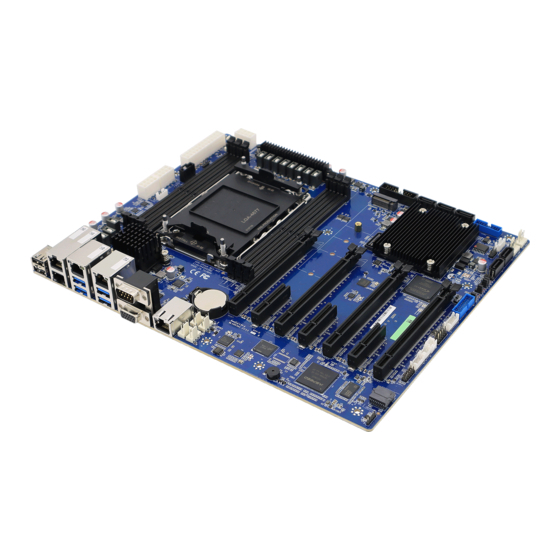
Page 19: Product Overview
User’s Manual 2.1 Product Overview HPM-SRSUA User’s Manual 19... -
Page 20: Jumper And Connector List
4 x 1 wafer, pitch 2.54mm SYS_FAN2 System fan connector 2 4 x 1 wafer, pitch 2.54mm SYS_FAN3 System fan connector 3 4 x 1 wafer, pitch 2.54mm SYS_FAN4 System fan connector 4 4 x 1 wafer, pitch 2.54mm 20 HPM-SRSUA User’s Manual... - Page 21 3 x 1 header, pitch 2.54mm JVR_PRG1 CASE OPEN connector 2 x 1 wafer, pitch 2.50mm JCASE_OPEN1 ATX 12V power connector 1 4 x 2 wafer, pitch 4.20mm ATX12V1 ATX12V2 ATX 12V power connector 2 4 x 2 wafer, pitch 4.20mm HPM-SRSUA User’s Manual 21...
- Page 22 CPU PCIE HP SMB connector 5 x 1 header, pitch 2.00mm JAUDIO1 AZALIA connector 6 x 2 header, pitch 2.00mm M2(NGFF)1 M.2 M-Key PCIe 3.0 x4 NVMe SSD JCPLD_JTAG1 CPLD JTAG header 5 x 2 header, pitch 2.54mm 22 HPM-SRSUA User’s Manual...
-
Page 23: Setting Jumpers & Connectors
User’s Manual 2.3 Setting Jumpers & Connectors 2.3.1 Flash Security Override (JPFLASHSEC) Disable* Enable * Default 2.3.2 ME FW update (JPME1) Normal* ME Force Update * Default HPM-SRSUA User’s Manual 23... -
Page 24: Force Pwron Setting (Jpallpwron1)
HPM-SRSUA User’s Manual 2.3.3 Force PWRON setting (JPALLPWRON1) Normal Operation* Enable Force PWR-ON * Default 2.3.4 Clear CMOS (JPBAT1) Normal Operation* Clear RTC REGISTERS * Default 24 HPM-SRSUA User’s Manual... -
Page 25: Boot Uart5 Setting (Jpboot_Uart5)
User’s Manual 2.3.5 Boot UART5 setting (JPBOOT_UART5) Disable* Enable BOOT FROM UART5 * Default 2.3.6 CPLD JTAG header (JCPLD_JTAG1) Signal PIN PIN Signal JTAG_TCK JTAG_TDO +3.3VSB JTAG_TMS JTAG_TDI HPM-SRSUA User’s Manual 25... -
Page 26: System Fan Connector 1 (Sys_Fan1)
HPM-SRSUA User’s Manual 2.3.7 System fan connector 1 (SYS_FAN1) Signal +12V FAN_TACH1 SYS_PWM1 2.3.8 System fan connector 2 (SYS_FAN2) Signal +12V FAN_TACH2 SYS_PWM2 26 HPM-SRSUA User’s Manual... -
Page 27: System Fan Connector 3 (Sys_Fan3)
User’s Manual 2.3.9 System fan connector 3 (SYS_FAN3) Signal +12V FAN_TACH3 SYS_PWM3 2.3.10 System fan connector 4 (SYS_FAN4) Signal +12V FAN_TACH4 SYS_PWM4 HPM-SRSUA User’s Manual 27... -
Page 28: System Fan Connector 5 (Sys_Fan5)
HPM-SRSUA User’s Manual 2.3.11 System fan connector 5 (SYS_FAN5) Signal +12V FAN_TACH5 SYS_PWM5 2.3.12 System fan connector 6 (SYS_FAN6) Signal +12V FAN_TACH6 SYS_PWM6 28 HPM-SRSUA User’s Manual... -
Page 29: Cpu Fan Connector (Cpu_Fan1)
User’s Manual 2.3.13 CPU fan connector (CPU_FAN1) Signal +12V FAN_TACH0 CPU0_PWM 2.3.14 SPI connector (JSPI1) Signal PIN PIN Signal +3.3VSB SPI_CS# SPI_CLK SPI_MISO SPI_MOSI SPI_IO3 SPI_IO2 HPM-SRSUA User’s Manual 29... -
Page 30: Serial Port 2 Connector (Jcom2)
HPM-SRSUA User’s Manual 2.3.15 Serial port 2 connector (JCOM2) Signal PIN PIN Signal COM_DCD#2 COM_RXD2 COM_TXD2 COM_DTR#2 COM_DSR#2 COM_RTS#2 COM_CTS#2 COM_RI#2 2.3.16 BMC_UART5 debug connector (JCOM5) Signal +3.3VSB UART5_RX UART5_TX 30 HPM-SRSUA User’s Manual... -
Page 31: Serial General Purpose I/O Connector (Jsgpio1)
User’s Manual 2.3.17 Serial General Purpose I/O connector (JSGPIO1) Signal PIN PIN Signal SGPIO_SATA0_DATA0 SGPIO_SATA0_LOAD SGPIO_SATA0_CLOCK 2.3.18 ATX 12V power connector 1 (ATX12V1) Signal Signal +12V +12V +12V +12V HPM-SRSUA User’s Manual 31... -
Page 32: Atx 12V Power Connector 2 (Atx12V2)
HPM-SRSUA User’s Manual 2.3.19 ATX 12V power connector 2 (ATX12V2) Signal Signal +12V +12V +12V +12V 2.3.20 ATX 12V power connector 3 (ATX12V3) Signal Signal +12V +12V +12V +12V 32 HPM-SRSUA User’s Manual... -
Page 33: Atx Power Connector (Atxpwr1)
User’s Manual 2.3.21 ATX power connector (ATXPWR1) Signal PIN PIN Signal +3.3V +3.3V +3.3V -12V PSON# PSU_PWRGD +V5SB +12V +12V +3.3V 2.3.22 Power supply PMBus connector (JPMBUS1) Signal SMB_PSU_SCL SMB_PSU_SDA SMB_PSU_ALERT# HPM-SRSUA User’s Manual 33... -
Page 34: Usb3.1 Gen1 Connector 1 (Jusb1)
USB3_RN4 USB3_RN5 USB3_RP4 USB3_RP5 USB3_TN4 USB3_TN5 USB3_TP4 USB3_TP5 USB3_PN8 USB3_PN9 USB3_PP8 USB3_PP9 USB_OC1# 2.3.24 USB3.1 Gen1 connector 2 (JUSB2) Signal PIN PIN Signal USB3_RN6 USB3_RN7 USB3_RP6 USB3_RP7 USB3_TN6 USB3_TN7 USB3_TP6 USB3_TP7 USB3_PN11 USB3_PN13 USB3_PP11 USB3_PP13 USB_OC2# 34 HPM-SRSUA User’s Manual... -
Page 35: Front Panel Connector (Jfp1)
User’s Manual 2.3.25 Front Panel connector (JFP1) Signal PIN PIN Signal LAN2-X_LED# LAN2-X_LED_P UID_BUTTON# UID_LED_P SBPWRLED_P UID_LED# LAN1_LED# STATUS_LED# LAN1_LED_P STATUS_LED_P PWRON_BUTTON# RESET_BUTTON# PWR_LED# HDD_LED# +3.3VSB HDD_LED_P 2.3.26 Inlet Thermal Sensor (JINLET_SER1) Signal +3.3VSB SMB_INLET_TEMPSENSOR_SDA SMB_INLET_TEMPSENSOR_SCL HPM-SRSUA User’s Manual 35... -
Page 36: Outlet Thermal Sensor (Joutlet_Ser1)
HPM-SRSUA User’s Manual 2.3.27 Outlet Thermal Sensor (JOUTLET_SER1) Signal +3.3VSB SMB_OUTLET_TEMPSENSOR_SDA SMB_OUTLET_TEMPSENSOR_SCL 2.3.28 HDD Backplane thermal Sensor (JHDD_SER1) Signal +3.3VSB SMB_HDBP_TEMPSENSOR_SDA SMB_HDBP_TEMPSENSOR_SCL SSD_LED_N 36 HPM-SRSUA User’s Manual... -
Page 37: Case Open Connector (Jcase_Open1)
User’s Manual 2.3.29 CASE OPEN connector (JCASE_OPEN1) Signal CHASSIS_INTRUSION 2.3.30 SATA RAID KEY connector (JRAID_KEY1) Signal PU_KEY_CONN PCH_SATA_RAIDKEY HPM-SRSUA User’s Manual 37... -
Page 38: Cpu Pcie Hp Smb Connector (Jpehpsmb1)
HPM-SRSUA User’s Manual 2.3.31 CPU PCIE HP SMB connector (JPEHPSMB1) Signal SMB_CPUHP_SCL SMB_CPUHP_SDA SMB_CPUHP_ALERT# 2.3.32 ESPI connector (JESPI1) Signal PIN PIN Signal ESPI_D0 +3.3VSB ESPI_D1 PLTRST# ESPI_D2 ESPI_CS# ESPI_D3 ESPI_CLK ESPI_RESET# ESPI_ALERT# 38 HPM-SRSUA User’s Manual... -
Page 39: Azalia Connector (Jaudio1)
User’s Manual 2.3.33 AZALIA connector (JAUDIO1) Signal PIN PIN Signal +3.3V AUD_AZA_SYNC AUD_AZA_BCLK AUD_AZA_SDO AUD_AZA_SDI0 AUD_AZA_SDI1 AUD_AZA_RST_N +5VSB 2.3.34 SMBUS VR connector (JVR_PRG1) Signal SMB_VR_SDA SMB_VR_SCL HPM-SRSUA User’s Manual 39... -
Page 40: Bios Setup
HPM-SRSUA User’s Manual 3.BIOS Setup 40 HPM-SRSUA User’s Manual... -
Page 41: Introduction
If the message disappears before you respond and you still wish to enter Setup, restart the system to try again by turning it OFF then ON or pressing the "RESET" button on the system case. You may also restart by simultaneously pressing <Ctrl>, <Alt>, and <Delete> keys. HPM-SRSUA User’s Manual 41... -
Page 42: Using Setup
Note: Some of the navigation keys differ from one screen to another. To Display a Sub Menu Use the arrow keys to move the cursor to the sub menu you want. Then press <Enter>. A “” pointer marks all sub menus. 42 HPM-SRSUA User’s Manual... -
Page 43: Getting Help
BIOS Vendor and your systems manufacturer to provide the absolute maximum performance and reliability. Even a seemingly small change to the chipset setup has the potential for causing you to use the override. HPM-SRSUA User’s Manual 43... -
Page 44: Bios Setup
Note: The BIOS setup screens shown in this chapter are for reference purposes only, and may not exactly match what you see on your screen. Visit the Avalue website (www.avalue.com.tw) to download the latest product and BIOS information. 44 HPM-SRSUA User’s Manual... -
Page 45: Advanced Menu
3.6.2.1 Trusted Computing Item Options Description Enables or Disables BIOS support for security device. Disable, Security Device Support O.S. will not show Security Device. TCG EFI protocol Enable[Default] and INT1A interface will not be available. HPM-SRSUA User’s Manual 45... -
Page 46: Acpi Settings
Enable ACPI Auto Disabled[Default] Enables or Disables BIOS ACPI Auto Configuration. Configuration Enabled Enables or Disables System ability to Hibernate Disabled Enable Hibernation (OS/S4 Sleep State). This option may not be effective Enabled[Default] with some operating systems. 46 HPM-SRSUA User’s Manual... -
Page 47: Ast2600 Super Io Configuration
Set Parameters of Serial Port 1 (COMA). Serial Port 2 Configuration Set Parameters of Serial Port 2 (COMB). 3.6.2.3.1 Serial Port 1 Configuration Item Option Description Enabled[Default], Serial Port Enable or Disable Serial Port (COM). Disabled HPM-SRSUA User’s Manual 47... -
Page 48: Serial Port 2 Configuration
HPM-SRSUA User’s Manual 3.6.2.3.2 Serial Port 2 Configuration Item Option Description Enabled[Default], Serial Port Enable or Disable Serial Port (COM). Disabled 3.6.2.4 Serial Port Console Redirection Item Options Description Disabled[Default], Console Redirection Console Redirection Enable or Disable. Enabled 48 HPM-SRSUA User’s Manual... -
Page 49: Com0
1 stop bit. Communication with slow devices may require more than 1 stoop bit. None[Default] Flow control can prevent data loss from buffer Flow Control Hardware RTS/CTS overflow. When sending data, if the receiving HPM-SRSUA User’s Manual 49... -
Page 50: Option Rom Dispatch Policy
Option ROM of Primary Video Device Disabled Primary Video Ignore will not dispatch, it will ignore this device policy Enabled[Default], settings, and restore it to ‘Enable’ automatically. Onboard Mass Storage Controller Enabled[Default], Onboard Device has: 50 HPM-SRSUA User’s Manual... - Page 51 Enable or Disable Option ROM execution for Slot#5 Empty Disabled selected Slot. Enabled[Default], Enable or Disable Option ROM execution for Slot#6 Empty Disabled selected Slot. Enabled[Default], Enable or Disable Option ROM execution for Slot#7 Empty Disabled selected Slot. HPM-SRSUA User’s Manual 51...
-
Page 52: Usb Configuration
Maximum time the device will take before it properly reports itself to the Host Controller. Auto[Default] ‘Auto’ uses default value: for a Root port it is Device power-up delay Manual 100 ms, for a Hub port the delay is taken from Hub descriptor. 52 HPM-SRSUA User’s Manual... -
Page 53: Network Stack Configuration
Optical drives are emulated as ‘CDROM’, drives with no media will be Hard Disk CD-ROM emulated according to a drive type. 3.6.2.7 Network Stack Configuration Item Options Description Enabled Network Stack Enable/Disable UEFI Network Stack. Disabled[Default] HPM-SRSUA User’s Manual 53... -
Page 54: Nvme Configuration
PXE boot. Use either +/- or numeric keys to set the value. Number of times the presence of media will be Media detect count checked. Use either +/- or numeric keys to set the value. 3.6.2.8 NVMe Configuration 54 HPM-SRSUA User’s Manual... -
Page 55: Platform Config
User’s Manual 3.6.3 Platform Config 3.6.3.1 PCH-IO Configuration Item Option Description Quiet[Default] Serial IRQ Mode Configure Serieal IRQ Mode. Continuous State After G3 S0 State Specify what state to go to when power is HPM-SRSUA User’s Manual 55... -
Page 56: Pci Express Configuration
For sucurity recommendations, SPD Enabled[Default] write disable bit must be set. 3.6.3.1.1 PCI Express Configuration Item Option Description Disabled[Default] PCI Express Port8xh Decode Port8xh Decode Enabled Enable/Disable. Disabled[Default] Enable when using Compliance Load Compliance Test Mode Enabled Board. 56 HPM-SRSUA User’s Manual... - Page 57 PCI Express Active State Power ASPM Management settings. Disabled[Default] L1.1 L1 Substates PCI Express L1 Substates settings. L1.2 L1.1 & L1.2 Enabled[Default], Enable/Disable Precision Time Disabled Measurement. Auto[Default] Gen1 PCIe Speed Configure PCIe Speed. Gen2 Gen3 HPM-SRSUA User’s Manual 57...
- Page 58 PCI Express Active State Power ASPM Management settings. Disabled[Default] L1.1 L1 Substates PCI Express L1 Substates settings. L1.2 L1.1 & L1.2 Enabled[Default], Enable/Disable Precision Time Disabled Measurement. Auto[Default] Gen1 PCIe Speed Configure PCIe Speed. Gen2 Gen3 58 HPM-SRSUA User’s Manual...
- Page 59 PCI Express Active State Power ASPM Management settings. Disabled[Default] L1.1 L1 Substates PCI Express L1 Substates settings. L1.2 L1.1 & L1.2 Enabled[Default], Enable/Disable Precision Time Disabled Measurement. Auto[Default] Gen1 PCIe Speed Configure PCIe Speed. Gen2 Gen3 HPM-SRSUA User’s Manual 59...
- Page 60 PCI Express Active State Power ASPM Management settings. Disabled[Default] L1.1 L1 Substates PCI Express L1 Substates settings. L1.2 L1.1 & L1.2 Enabled[Default], Enable/Disable Precision Time Disabled Measurement. Auto[Default] Gen1 PCIe Speed Configure PCIe Speed. Gen2 Gen3 60 HPM-SRSUA User’s Manual...
-
Page 61: Sata And Rst Configuration
User’s Manual 3.6.3.1.2 SATA And RST Configuration 3.6.3.1.2.1 Controller 2 SATA And RST Configuration Item Options Description Enabled[Default] SATA Configuration SATA test settings. Disabled, HPM-SRSUA User’s Manual 61... - Page 62 Otherwise all drives spin up at boot. Hard Disk Drive[Default] Identify the SATA port is connected to Solid SATA Device Type Solid State Drive State Drive or Hard Disk Drive. 62 HPM-SRSUA User’s Manual...
- Page 63 Enable SATA DevSlp feature for port. It is SATA DevSlp port Port3 possible to enable DevSlp for only one port or Port4 none. Port5 Port6 Port7 Disabled SATA Port 0(Onboard SATA1) Enable or Disable SATA Port. Enabled[Default] HPM-SRSUA User’s Manual 63...
- Page 64 Otherwise all drives spin up at boot. Hard Disk Drive[Default] Identify the SATA port is connected to Solid SATA Device Type Solid State Drive State Drive or Hard Disk Drive. 64 HPM-SRSUA User’s Manual...
- Page 65 OS is enabled. If enabled, indicates that the LED/SGPIO Disabled, LED Locate hardware is attached and ping to locate Enabled[Default] feature is enabled on the OS. 3.6.3.1.2.4 Software Feature Mask Configuration for Controller 3 HPM-SRSUA User’s Manual 65...
-
Page 66: Usb Configuration
USB Overcurrent Lock used. Enabling this will make xHCI controller Enabled[Default] consume the Overcurrent mapping data. Selectively Enable/Disable the corresponding USB Disabled[Default] USB Port Disable Override port from reporting a Device Connection to the Select Per-Pin controller. 66 HPM-SRSUA User’s Manual... -
Page 67: Hd Audio Configuration
User’s Manual 3.6.3.1.4 HD Audio Configuration Item Options Description Control Detection of the HD-Audio device. Disabled, HD Audio Disabled=HDA will be unconditionally disabled Enabled[Default] Enabled=HDA will be unconditionally enabled. 3.6.3.2 Server ME Configuration HPM-SRSUA User’s Manual 67... -
Page 68: Socket Config
Provide the 8000h value if the altitude is unknown. MCTP bus owner location on PCIe: [15:8] bus, [7:3] MCTP Bus Owner device, [2:0] function. If all zeros sending bus owner is disabled. 3.6.4 Socket Config 68 HPM-SRSUA User’s Manual... -
Page 69: Processor Configuration
User’s Manual 3.6.4.1 Processor Configuration Item Option Description Enable/disable extended APIC support. Disable Extended APIC Note: When enabled, VT-d_Interrupt Enable[Default] Remapping will be automatically enabled. 3.6.4.1.1 Per-Socket Configuration HPM-SRSUA User’s Manual 69... -
Page 70: Cpu Socket 0 Configuration
CPU Socket 0 Configuration Item Option Description 0: Enable all cores. FFFFFFFFFFFFFFFF: Disable all cores. NOTE: AT least one core per CPU must be Disable Bitmap: enabled. Disabling all cores is an invalid configuration. 3.6.4.2 Memory Configuration 70 HPM-SRSUA User’s Manual... -
Page 71: Memory Topology
MT/s. If Enforce POR is disabled, user will 4000 Memory Frequency be able to run at higher frequencies than 4400 the memory suppot (limited by processor 4800 support). Do not select Reserved. 5200 5600 3.6.4.2.1 Memory Topology 3.6.4.3 IIO Configuration HPM-SRSUA User’s Manual 71... -
Page 72: Socket0 Configuration
Auto Selects PCIe port Bifurcation for selected x4x4x4x4 IOU1 PCIe Slot3 x16 x4x4x_x8 slot(s) Port Format: xDxCxBxA The port x_x8x4x4 can further be x2x2. x_x8x_x8 72 HPM-SRSUA User’s Manual... - Page 73 Auto x4x4x4x4 x4x4x_x8 x_x8x4x4 Selects PCIe port Bifurcation for selected x_x8x_x8 IOU3 PCIe Slot7 x16 x_x_x_x16[Default] slot(s) Port Format: xDxCxBxA The port x2x2x4x_x8 can further be x2x2. x4x2x2x_x8 x_x8x2x2x4 x2x2x4x4x4 x4x2x2x4x4 HPM-SRSUA User’s Manual 73...
- Page 74 Select PCIe Subsystem Mode for selected slot(s) Gen4: Gen4 controller Gen5 Port 2 Subsystem Mode only Gen5: Gen5 with or without mix Protocol Auto Negotiation[Default] mode Auto: Auto select Force CXL: There is no training discovery, the attached 74 HPM-SRSUA User’s Manual...
- Page 75 Applies to root ports only. Enabled Sck0 RP NonFatal No[Default] Uncorrectable Err interrupt on a non-fatal error. Applies to root ports only. Enabled Sck0 RP Fatal No[Default] Uncorrectable Err MSI/INTx interrupt on fatal errors. HPM-SRSUA User’s Manual 75...
-
Page 76: Port Dmi
Gen 5 (32 GT/s) -6.0 dB[Default] De-Emphais control (LNKCON2[6]) for this PCIe PCI-E Port DeEmphasis -3.5 dB port. Disabled[Default] This option can disable ASPM support in a PCIe PCI-E ASPM Support root port. ‘Auto’ keeps hardware default. Auto 76 HPM-SRSUA User’s Manual... -
Page 77: Port 1A(Pcie Slot1)
Configure Max Payload Size Supported in PCIe 256B Device Capabilities register. ‘Auto’ keeps hardware PCI-E Port MPSS 512B default. Auto[Default] Disabled[Default] This option can disable ASPM support in a PCIe PCI-E ASPM Support root port. ‘Auto’ keeps hardware default. Auto HPM-SRSUA User’s Manual 77... -
Page 78: Port 2A(Pcie Slot3)
Link Speed Choose Link Speed for this PCIe port. Gen 3 (8 GT/s) Gen 4 (16 GT/s) Gen 5 (32 GT/s) Auto[Default] Override the max link width that was set by Override Max Link Width bifurcation. 78 HPM-SRSUA User’s Manual... -
Page 79: Port 3A(Pcie Slot5)
In auto mode the BIOS will remove the EXP port if Auto[Default] there is no device or errors on that device and the PCI-E Port device is not HP capable. Enable/Disable is used to enable/disable the port and expose/hide its CFG space. HPM-SRSUA User’s Manual 79... - Page 80 Compliance Mode port. MCTP Enable/Disable MCTP. Yes[Default] Equalization Bypass To Disable Equalization Bypass To Highest Rate Support Highest Rate Enable[Default] Enable/Disable. Disable[Default] Enable/Disable CXL Drift Buffer if there is a CXL Drift Buffer Enable common referecne clock. 80 HPM-SRSUA User’s Manual...
-
Page 81: Port 4A(Pcie Slot7)
Configure Max Payload Size Supported in PCIe 256B Device Capabilities register. ‘Auto’ keeps hardware PCI-E Port MPSS 512B default. Auto[Default] Disabled[Default] This option can disable ASPM support in a PCIe PCI-E ASPM Support root port. ‘Auto’ keeps hardware default. Auto HPM-SRSUA User’s Manual 81... -
Page 82: Port 5A(X550)
Link Speed Choose Link Speed for this PCIe port. Gen 3 (8 GT/s) Gen 4 (16 GT/s) Gen 5 (32 GT/s) Auto[Default] Override the max link width that was set by Override Max Link Width bifurcation. 82 HPM-SRSUA User’s Manual... -
Page 83: Port 5C(Pcie Slot2)
In auto mode the BIOS will remove the EXP port if Auto[Default] there is no device or errors on that device and the PCI-E Port device is not HP capable. Enable/Disable is used to enable/disable the port and expose/hide its CFG HPM-SRSUA User’s Manual 83... - Page 84 Compliance Mode port. MCTP Enable/Disable MCTP. Yes[Default] Equalization Bypass To Disable Equalization Bypass To Highest Rate Support Highest Rate Enable[Default] Enable/Disable. Disable[Default] Enable/Disable CXL Drift Buffer if there is a CXL Drift Buffer Enable common referecne clock. 84 HPM-SRSUA User’s Manual...
-
Page 85: Port 5E(Pcie Slot4)
Configure Max Payload Size Supported in PCIe 256B Device Capabilities register. ‘Auto’ keeps hardware PCI-E Port MPSS 512B default. Auto[Default] Disabled[Default] This option can disable ASPM support in a PCIe PCI-E ASPM Support root port. ‘Auto’ keeps hardware default. Auto HPM-SRSUA User’s Manual 85... -
Page 86: Port 5G(Pcie Slot6)
Link Speed Choose Link Speed for this PCIe port. Gen 3 (8 GT/s) Gen 4 (16 GT/s) Gen 5 (32 GT/s) Auto[Default] Override the max link width that was set by Override Max Link Width bifurcation. 86 HPM-SRSUA User’s Manual... -
Page 87: Intel Vt For Directed I/O (Vt-D)
Description Eneble/Disable Intel Virtualization Technology for Directed I/O (VT-d) by reporting the I/O device Enable[Default] Intel VT for Directed I/O Disable assignment to VMM through DMAR ACPI Tables. To disable VT-d, X2APIC must also be disabled. HPM-SRSUA User’s Manual 87... -
Page 88: Intel Vmd Technology
HPM-SRSUA User’s Manual 3.6.4.3.3 Intel VMD technology 3.6.4.3.3.1 Intel VMD for Volume Management Device on Socket 0 Item Option Description Disable[Default] Enable/Disable VMD Enable/Disable VMD in this Stack. Enable 88 HPM-SRSUA User’s Manual... - Page 89 Setup VMD Memory BAR2 size (in bits MemBar2 size Min=20), ex:20bits=1MB, 22bits=4MB, 26bits=64MB. 32-bit non-prefetchable Setup VMD Config BAR2 attribute, like MemBar2 attribute 64-bit non-prefetchable 64-bit or prefectchable. 64-bit prefetchable[Default] Disable[Default] VMD for Direct Assign Enable/Disable VMD for Direct Assign. Enable HPM-SRSUA User’s Manual 89...
- Page 90 VMD port G Management Device Technology on Enable specific root port. Enable/Disable Intel Volume Disable[Default] VMD port H Management Device Technology on Enable specific root port. Disable[Default] Enable/Disable Hot Plug for PCIe Root Hot Plug Capable Enable Ports. 90 HPM-SRSUA User’s Manual...
- Page 91 Disable[Default] Enable/Disable VMD Enable/Disable VMD in this Stack. Enable Enable/Disable Intel Volume Disable[Default] VMD port A Management Device Technology on Enable specific root port. Disable[Default] Enable/Disable Intel Volume VMD port B Enable Management Device Technology on HPM-SRSUA User’s Manual 91...
- Page 92 Setup VMD Memory BAR2 size (in bits MemBar2 size Min=20), ex:20bits=1MB, 22bits=4MB, 26bits=64MB. 32-bit non-prefetchable Setup VMD Config BAR2 attribute, like MemBar2 attribute 64-bit non-prefetchable 64-bit or prefectchable. 64-bit prefetchable[Default] Disable[Default] VMD for Direct Assign Enable/Disable VMD for Direct Assign. Enable 92 HPM-SRSUA User’s Manual...
- Page 93 VMD port G Management Device Technology on Enable specific root port. Enable/Disable Intel Volume Disable[Default] VMD port H Management Device Technology on Enable specific root port. Disable[Default] Enable/Disable Hot Plug for PCIe Root Hot Plug Capable Enable Ports. HPM-SRSUA User’s Manual 93...
- Page 94 Enable/Disable VMD in this Stack. Enable[Default] Enable/Disable Intel Volume Disable[Default] VMD port A Management Device Technology on Enable specific root port. Enable/Disable Intel Volume Disable[Default] VMD port B Management Device Technology on Enable specific root port. 94 HPM-SRSUA User’s Manual...
- Page 95 Setup VMD Memory BAR2 size (in bits MemBar2 size Min=20), ex:20bits=1MB, 22bits=4MB, 26bits=64MB. 32-bit non-prefetchable Setup VMD Config BAR2 attribute, like MemBar2 attribute 64-bit non-prefetchable 64-bit or prefectchable. 64-bit prefetchable[Default] Disable[Default] VMD for Direct Assign Enable/Disable VMD for Direct Assign. Enable HPM-SRSUA User’s Manual 95...
- Page 96 VMD port G Management Device Technology on Enable specific root port. Enable/Disable Intel Volume Disable[Default] VMD port H Management Device Technology on Enable specific root port. Disable[Default] Enable/Disable Hot Plug for PCIe Root Hot Plug Capable Enable Ports. 96 HPM-SRSUA User’s Manual...
-
Page 97: Advanced Power Management Configuration
Min=20), ex:20bits=1MB, 22bits=4MB, 26bits=64MB. 32-bit non-prefetchable Setup VMD Config BAR2 attribute, like MemBar2 attribute 64-bit non-prefetchable 64-bit or prefectchable. 64-bit prefetchable[Default] Disable[Default] VMD for Direct Assign Enable/Disable VMD for Direct Assign. Enable 3.6.4.4 Advanced Power Management Configuration HPM-SRSUA User’s Manual 97... -
Page 98: Cpu P State Control
Set by Intel Node Manager Enable[Default] Energy Efficient Turbo Disable, MSR Energy Efficient Turbo Disable 0x1FC[19]. Disable Enable/Disable processor Turbo Mode Turbo Mode Enable[Default] (requires EMTTM enabled too). Disable[Default] Enable/Disable CPU Flex Ratio CPU Flex Ratio Override Enable Programming. 98 HPM-SRSUA User’s Manual... -
Page 99: Cpu C State Control
Core C1E auto promotion Control. Takes Disable effect after reboot. Will be enforced to Enhanced Halt State (C1E) Enable[Default] enable when Optimized Power Mode is enabled. ACPI C2[Default] Report CC3/CC6 to OS ACPI C2 or ACPI OS ACPI Cx ACPI C3 HPM-SRSUA User’s Manual 99... -
Page 100: Server Mgmt
Power Cycle disabled. If enabled, starts a BIOS timer which can only be shut Enabled OS Watchdog Timer off by Management Software after the OS loads. Helps Disabled[Default] determine that the OS successfully loaded or follows 100 HPM-SRSUA User’s Manual... -
Page 101: System Event Log
Choose options for reactions to a full SEL. Delete Oldest Record Disabled Both Disable the logging of EFI Status Codes or log Log EFI Status Codes Error code[Default] only error code or only progress code or both. Progress code HPM-SRSUA User’s Manual 101... -
Page 102: Bmc Self Test Log
Bmc self test log Item Option Description Yes, On every reset[Default] Erase Log Erase Log Options. Clear Log[Default] When log is full Select the action to be taken when log is full. Do not log any more 102 HPM-SRSUA User’s Manual... -
Page 103: Bmc Network Configuration
Select configure LAN channel parameters Configuration Address Static statically or dynamically(by BIOS or BMC). source DynamicBmcDhcp Unspecified option will not modify any BMC DynamicBmcNonDhcp network parameters during BIOS phase. Enabled[Default] IPV6 Support Enable or Disable LAN1 IPv6 Support. Disabled HPM-SRSUA User’s Manual 103... -
Page 104: Bmc User Settings
Unspecified[Default] Configuration Router Lan1 statically or dynamically (by BIOS or BMC). Static Address source Unspecified option will not modify any BMC DynamicBmcDhcp network parameters during BIOS phase. 3.6.5.4 BMC User Settings 3.6.5.4.1 BMC Add User Details 104 HPM-SRSUA User’s Manual... -
Page 105: Bmc Delete User Details
User’s Manual Item Description User Name Enter BMC User Name. 3.6.5.4.2 BMC Delete User Details Item Description User Name Enter BMC User Name. 3.6.5.4.3 BMC Change User Settings HPM-SRSUA User’s Manual 105... -
Page 106: Security
HPM-SRSUA User’s Manual Item Description User Name Enter BMC User Name. 3.6.6 Security Administrator Password Set setup Administrator Password User Password Set User Password 106 HPM-SRSUA User’s Manual... -
Page 107: Secure Boot
User’s Manual 3.6.6.1 Secure Boot 3.6.7 Boot HPM-SRSUA User’s Manual 107... - Page 108 Set the system boot order. USB Device Network Disabled Hard Disk NVME CD/DVD[Default] Boot Option #3 Set the system boot order. USB Device Network Disabled Hard Disk Boot Option #4 Set the system boot order. NVME 108 HPM-SRSUA User’s Manual...
-
Page 109: Save And Exit
Optimized Boot. 3.6.8 Save and exit 3.6.8.1 Save Changes and Exit Use the save changes and reset option to save the changes made to the BIOS options and to exit the BIOS configuration setup program. HPM-SRSUA User’s Manual 109... -
Page 110: Discard Changes And Exit
This option saves a copy of the current BIOS settings as the User Defaults. This option is useful for preserving custom BIOS setup configurations. 3.6.8.9 Restore User Defaults This option restores all BIOS settings to the user defaults. This option is useful for restoring previously preserved custom BIOS setup configurations. 110 HPM-SRSUA User’s Manual... -
Page 111: Drivers Installation
User’s Manual 4. Drivers Installation Note: Installation procedures and screen shots in this section are for your reference and may not be exactly the same as shown on your screen. HPM-SRSUA User’s Manual 111... -
Page 112: Install Chipset Driver
Windows 10 operation system. If the warning message appears while the installation process, click Continue to go on. Step 3. Click Install. Step1. Click Next. Step 4. Setup completed. Step 2. Click Accept. 112 HPM-SRSUA User’s Manual... -
Page 113: Install Vga Driver
Note: The installation procedures and screen shots in this section are based on Windows 10 operation system. Step 3. Click Next. Step 1. Click Next to continue installation. Step 4. Click Next. Step 2. Click Next. Step 5. Click Install. HPM-SRSUA User’s Manual 113... - Page 114 HPM-SRSUA User’s Manual Step 6. Click Finish to complete setup. 114 HPM-SRSUA User’s Manual...
-
Page 115: Install Audio Driver
All drivers can be found on the Avalue Official Website: http://www.avalue.com.tw. Note: The installation procedures and screen shots in this section are based on Windows 10 operation system. Step 1. Click Yes to continue installation. Step 2. Setup completed. HPM-SRSUA User’s Manual 115... -
Page 116: Install Ethernet Driver
All drivers can be found on the Avalue Official Website: http://www.avalue.com.tw. Note: The installation procedures and screen shots in this section are based on Windows 10 operation system. Step 1. Click OK to continue installation. Step 2. Setup completed. 116 HPM-SRSUA User’s Manual... -
Page 117: Install Quickassist Technology Driver
Windows 10 operation system. Step 3. Click Next. Step 1. Click Next to continue installation. Step 4. Click Install. Step 2. Click Next. Step 5. Click Finish to complete setup. HPM-SRSUA User’s Manual 117... -
Page 118: Install Vroc Driver
Note: The installation procedures and screen shots in this section are based on Windows 10 operation system. Step 3. Click Accept. Step 1. Click Install to continue installation. Step 4. Click Next. Step 2. Click Next. Step 5. Click Install. 118 HPM-SRSUA User’s Manual... - Page 119 User’s Manual Step 6. Setup completed. HPM-SRSUA User’s Manual 119...
-
Page 120: Mechanical Drawing
HPM-SRSUA User’s Manual 5. Mechanical Drawing 120 HPM-SRSUA User’s Manual... - Page 121 User’s Manual Unit: mm HPM-SRSUA User’s Manual 121...
Need help?
Do you have a question about the HPM-SRSUA and is the answer not in the manual?
Questions and answers