
Related Manuals for Avalue Technology HPM-246UA


Summary of Contents for Avalue Technology HPM-246UA
- Page 1 HPM-246 Intel® LGA1151 Socket Supports 8th/9th Generation Core™ i7/ i5/ i3 / Pentium® /Celeron® / Xeon® E Process User’s Manual Ed –17 August 2021 DMR Number: T55752-00 Part No: E2047IG4602R Rev: 3...
- Page 2 HPM-246 User’s Manual FCC Statement THIS DEVICE COMPLIES WITH PART 15 FCC RULES. OPERATION IS SUBJECT TO THE FOLLOWING TWO CONDITIONS: (1) THIS DEVICE MAY NOT CAUSE HARMFUL INTERFERENCE. (2) THIS DEVICE MUST ACCEPT ANY INTERFERENCE RECEIVED INCLUDING INTERFERENCE THAT MAY CAUSE UNDESIRED OPERATION. THIS EQUIPMENT HAS BEEN TESTED AND FOUND TO COMPLY WITH THE LIMITS FOR A CLASS "A"...
- Page 3 User’s Manual these products are free from patent, copyright, or mask work right infringement, unless otherwise specified. Applications that are described in this manual are for illustration purposes only. We make no representation or warranty that such application will be suitable for the specified use without further testing or modification.
- Page 4 HPM-246 User’s Manual Product Warranty We warrant to you, the original purchaser, that each of its products will be free from defects in materials and workmanship for two years from the date of purchase. This warranty does not apply to any products which have been repaired or altered by persons other than repair personnel authorized, or which have been subject to misuse, abuse, accident or improper installation.
-
Page 5: Table Of Contents
User’s Manual Content Getting Started ......................8 Safety Precautions ....................8 Packing List ....................... 8 Document Amendment History ................. 9 Manual Objectives ....................10 System Specifications ..................... 11 Architecture Overview—Block Diagram ..............13 Hardware Configuration ................... 14 Product Overview ....................15 Jumper and Connector List .................. - Page 6 HPM-246 User’s Manual 2.3.26 VGA connector (JVGA1) ......................30 2.3.27 For BMC debug message read (JBMC_UART5) ............... 31 2.3.28 CASE OPEN connector (JCASE_OPEN1) ................31 2.3.29 Audio connector (JAUDIO1) ...................... 32 Signal Description – Audio connector (JAUDIO1) ..............32 2.3.29.1 3.BIOS Setup ........................
- Page 7 User’s Manual 3.6.3.2 PCH-IO Configuration ......................56 3.6.3.2.1 PCI Express Configuration ....................56 3.6.3.2.2 SATA And RST Configuration ....................68 3.6.3.2.3 HD Audio Configuration ......................69 3.6.3.3 Board Configuration ......................69 3.6.4 Server Mgmt ..........................70 3.6.4.1 System Event Log ........................ 71 3.6.4.2 Bmc self test log........................
-
Page 8: Getting Started
HPM-246 User’s Manual Getting Started 1.1 Safety Precautions Warning! Always completely disconnect the power cord from your chassis whenever you work with the hardware. Do not make connections while the power is on. Sensitive electronic components can be damaged by sudden power surges. -
Page 9: Document Amendment History
User’s Manual 1.3 Document Amendment History Revision Date Comment January 2020 Initial Release May 2020 Update BIOS setup August 2021 Update 2.3 Setting Jumpers & Connectors HPM-246 User’s Manual... -
Page 10: Manual Objectives
HPM-246 User’s Manual 1.4 Manual Objectives We have tried to include as much information as possible but we have not duplicated information that is provided in the standard IBM Technical References, unless it proved to be necessary to aid in the understanding of this board. We strongly recommend that you study this manual carefully before attempting to set up HPM-246 or change the standard configurations. -
Page 11: System Specifications
User’s Manual 1.5 System Specifications System Intel® LGA1151 Socket Supports 8th/9th Generation Core™ i7/ i5/ i3 / Pentium® /Celeron® / Xeon® E Process BIOS AMI uEFI BIOS, 256Mbit SPI Flash ROM System Chipset Intel® C246 I/O Chip Nuvoton NCT6106D 4 x 288-pin DDR4 2666MHz DIMM supports up to 128GB (ECC memory supported System Memory by CPU) Watchdog Timer... - Page 12 HPM-246 User’s Manual 2 x 2 x 5 pin, pitch 2.0mm RS232 Box Header Onboard buzzer 1 x 2 x 12 pin, pitch 4.2mm ATX power connector 1 x 2 x 4 pin, pitch 4.2mm ATX 12V power connector 1 x 2 x 5 pin, pitch 2.54mm connector for front Audio Display Graphic Chipset Intel®...
-
Page 13: Architecture Overview-Block Diagram
User’s Manual 1.6 Architecture Overview—Block Diagram The following block diagram shows the architecture and main components of HPM-246. HPM-246 User’s Manual 13... -
Page 14: Hardware Configuration
HPM-246 User’s Manual 2. Hardware Configuration 14 HPM-246 User’s Manual... -
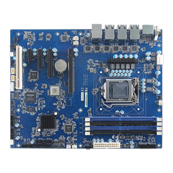
Page 15: Product Overview
User’s Manual 2.1 Product Overview HPM-246 User’s Manual 15... -
Page 16: Jumper And Connector List
HPM-246 User’s Manual 2.2 Jumper and Connector List You can configure your board to match the needs of your application by setting jumpers. A jumper is the simplest kind of electric switch. It consists of two metal pins and a small metal clip (often protected by a plastic cover) that slides over the pins to connect them. - Page 17 User’s Manual JCOM2 Serial Port 2 connector 5 x 2 wafer, pitch 2.00mm Rear General purpose I/O connector JSGPIO1 3 x 2 wafer, pitch 2.00mm (Reserved) PCIEX1 PCIEx16 connector PCIEX2 PCIEx8 connector PCIEX3 PCIEx1 connector PCIEX4 PCIEx4 connector PCI1 PCI connector Rear System Error LED Display Port connector 1 DP2/3...
-
Page 18: Setting Jumpers & Connectors
HPM-246 User’s Manual 2.3 Setting Jumpers & Connectors 2.3.1 PM BUS pull high Jumper (PH1) Read power supply information* PM BUS non pull high with 3.3V * Default 2.3.2 Flash BIOS ME connector (JME1) Normal* Override * Default 18 HPM-246 User’s Manual... -
Page 19: Bmc Strap Setting (Bmc_Db1)
User’s Manual 2.3.3 BMC strap setting (BMC_DB1) ENABLE PASS-THRU AT POWER ON ENABLE DEDICATED VGA BIOS ROM ENABLE BOOT RESET BMC * Default 2.3.4 Clear CMOS (JCMOS1) Normal* Clear CMOS * Default HPM-246 User’s Manual 19... -
Page 20: Cpu Fan Connector (Cpu_Fan1)
HPM-246 User’s Manual 2.3.5 CPU fan connector (CPU_FAN1) Signal +12V FAN_TACH0 CPU0_PWM0 2.3.6 Outlet fan connector 1 (SYS_FAN1) Signal +12V FAN_TACH2 SYS_PWM2 20 HPM-246 User’s Manual... -
Page 21: Outlet Fan Connector 2 (Sys_Fan2)
User’s Manual 2.3.7 Outlet fan connector 2 (SYS_FAN2) Signal +12V FAN_TACH3 SYS_PWM3 2.3.8 Inlet fan connector (SYS_FAN3) Signal +12V FAN_TACH4 SYS_PWM4 HPM-246 User’s Manual 21... -
Page 22: Serial Port 1 Connector (Jcom1)
HPM-246 User’s Manual 2.3.9 Serial port 1 connector (JCOM1) Signal PIN PIN Signal COM_DCD#1 COM_RXD1 COM_TXD1 COM_DTR#1 COM_DSR#1 COM_RTS#1 COM_CTS#1 COM_RI#1 2.3.10 Serial port 2 connector (JCOM2) Signal PIN PIN Signal COM_DCD#2 COM_RXD2 COM_TXD2 COM_DTR#2 COM_DSR#2 COM_RTS#2 COM_CTS#2 COM_RI#2 22 HPM-246 User’s Manual... -
Page 23: General Purpose I/O Connector (Jsgpio1)
User’s Manual 2.3.11 General purpose I/O connector (JSGPIO1) Signal PIN PIN Signal SGPIO_SSATA_DATA0_R SGPIO_SSATA_LOAD_R SGPIO_SSATA_CLOCK_R 2.3.12 LPC connector (JLPC1) Signal PIN PIN Signal LPC_AD0 +3.3V LPC_AD1 PLT_RST#_BUF LPC_AD2 LPC_FRAME# LPC_AD3 LPC_DEG_CLK LPC_SERIRQ HPM-246 User’s Manual 23... -
Page 24: Atx 12V Power Connector (Atx12V1)
HPM-246 User’s Manual 2.3.13 ATX 12V Power connector (ATX12V1) Signal Signal +12V +12V +12V +12V 2.3.14 ATX Power connector (ATXPWR1) Signal PIN PIN Signal +3.3V +12V +12V +5VSB ATX24_PWROK 16 ATX_PSON# +3.3V -12V +3.3V +3.3V 24 HPM-246 User’s Manual... -
Page 25: Usb3.1 Connector (Jusb34)
User’s Manual 2.3.15 USB3.1 connector (JUSB34) Signal PIN PIN Signal +5VSB +5VSB USB30_RX_N3 USB30_RX_N4 18 USB30_RX_P3 USB30_RX_P4 17 USB30_TXN3 USB30_TXN4 USB30_TXP3 USB30_TXP4 USB_N3 USB_N4 USB_P3 USB_P4 2.3.16 USB3.1 connector (JUSB56) Signal PIN PIN Signal +5VSB +5VSB USB30_RX_N5 USB30_RX_N6 18 USB30_RX_P5 USB30_RX_P6 17 USB30_TXN5 USB30_TXN6... -
Page 26: Usb3.1 Connector (Jusb78)
HPM-246 User’s Manual 2.3.17 USB3.1 connector (JUSB78) Signal PIN PIN Signal +5VSB +5VSB USB30_RX_N7 USB30_RX_N8 18 USB30_RX_P7 USB30_RX_P8 17 USB30_TXN7 USB30_TXN8 USB30_TXP7 USB30_TXP8 USB_N7 USB_N8 USB_P7 USB_P8 2.3.18 SPI connector 1 (JSPI1) Signal PIN PIN Signal +3.3VSB SPI_BIOS_CS0_N_R SPI_BIOS_FLASH_CLK SPI_BIOS_MISO_FLASH SPI_BIOS_MOSI_FLASH SPI_PCH_FLASH_IO3 SPI_PCH_FLASH_IO2... -
Page 27: Spi Connector 2 (Jspi2)
User’s Manual 2.3.19 SPI connector 2 (JSPI2) Signal PIN PIN Signal +3.3VSB SPI_BMC_BOOT_CS_N SPI_BMC_BOOT_CLK SPI_BMC_BOOT_R_MISO SPI_BMC_BOOT_MOSI SPI_HOLD# SPI_WP# 2.3.20 Debug connector (JDEBUG1) Signal PEX_I2C_SCL0_3V3 PEX_I2C_SDA0_3V3 HPM-246 User’s Manual 27... -
Page 28: Front Panel Connector (Jfp1)
HPM-246 User’s Manual 2.3.21 Front Panel connector (JFP1) Signal PIN PIN Signal HDD_LED_P PWR_LED+ HDD_LED_N PWR_LED- FP_RST_BTN_N FP_PWR_BTN_N_R STATUS_LED2_P 10 L1_LED_ACT#_PWR STATUS_LED_N L1_LED_ACT# FRONT_UID_LED_N 13 SBPWRLED_P FP_UID_BTN_N_R +3.3VSB LAN_LED_ACT# 2.3.22 Read power supply information (PMBUS1) Signal PSU1_ALERT_z_N PSU_z_SDA PSU_z_SCL 28 HPM-246 User’s Manual... -
Page 29: For Eeprom Write Data (Jp1)
User’s Manual 2.3.23 For EEPROM write data (JP1) Signal +3.3VSB BMC_SCL13_R BMC_SDA13_R 24C02_WP 2.3.24 For VCORE PWM FW write data (JP2) Signal PIN PIN Signal VCCCORE_Npmalert VCCCORE_PMSDA VCCCORE_PMSCL +3.3V HPM-246 User’s Manual 29... -
Page 30: Inlet Thermal Sensors (Inlet_Ser1)
HPM-246 User’s Manual 2.3.25 Inlet Thermal Sensors (INLET_SER1) Signal +3.3VSB SMB1_TEMPSENSOR_STBY_LVC3_SDA SMB1_TEMPSENSOR_STBY_LVC3_SCL 2.3.26 VGA connector (JVGA1) Signal PIN PIN Signal CRT_z_RED CRT_z_GREEN CRT_z_BLUE CRT_DDC_z_DATA CRT_z_HSYNC 10 VIDEO_CABLE_DETECT_N CRT_z_VSYNC CRT_DDC_z_CLK 30 HPM-246 User’s Manual... -
Page 31: For Bmc Debug Message Read (Jbmc_Uart5)
User’s Manual 2.3.27 For BMC debug message read (JBMC_UART5) Signal UART5_TX UART5_RX 2.3.28 CASE OPEN connector (JCASE_OPEN1) Signal FP_CHASSIS_INTRUSION HPM-246 User’s Manual 31... -
Page 32: Audio Connector (Jaudio1)
HPM-246 User’s Manual 2.3.29 Audio connector (JAUDIO1) Signal PIN PIN Signal MIC1-L-IN MIC1-R-IN ACZ_DET# FRONT-R-OUT MIC1-JD SENSEA FRONT-L-OUT FRONT-JD 2.3.29.1 Signal Description – Audio connector (JAUDIO1) Signal Signal Description FRONT-JD AUDIO Out(ROUT/LOUT) sense pin MIC1-JD MIC IN (MIC_RIN/LIN) sense pin 32 HPM-246 User’s Manual... -
Page 33: Bios Setup
User’s Manual 3.BIOS Setup HPM-246 User’s Manual 33... -
Page 34: Introduction
HPM-246 User’s Manual 3.1 Introduction The BIOS setup program allows users to modify the basic system configuration. In this following chapter will describe how to access the BIOS setup program and the configuration options that may be changed. 3.2 Starting Setup AMI BIOS™... -
Page 35: Using Setup
User’s Manual 3.3 Using Setup In general, you use the arrow keys to highlight items, press <Enter> to select, use the PageUp and PageDown keys to change entries, press <F1> for help and press <Esc> to quit. The following table provides more detail about how to navigate in the Setup program using the keyboard. -
Page 36: Getting Help
HPM-246 User’s Manual 3.4 Getting Help Press F1 to pop up a small help window that describes the appropriate keys to use and the possible selections for the highlighted item. To exit the Help Window press <Esc> or the <Enter> key again. 3.5 In Case of Problems If, after making and saving system changes with Setup, you discover that your computer no longer is able to boot, the AMI BIOS supports an override to the NVRAM settings which... -
Page 37: Bios Setup
User’s Manual 3.6 BIOS setup Once you enter the Aptio Setup Utility, the Main Menu will appear on the screen. The Main Menu allows you to select from several setup functions and exit choices. Use the arrow keys to select among the items and press <Enter> to accept and enter the sub-menu. 3.6.1 Main Menu This section allows you to record some basic hardware configurations in your computer and set the system clock. -
Page 38: System Language
HPM-246 User’s Manual 3.6.1.1 System Language This option allows choosing the system default language. 3.6.1.2 System Date Use the system date option to set the system date. Manually enter the day, month and year. 3.6.1.3 System Time Use the system time option to set the system time. Manually enter the hours, minutes and seconds. -
Page 39: Cpu Configuration
User’s Manual 3.6.2.1 CPU Configuration Use the CPU configuration menu to view detailed CPU specification and configure the CPU. Item Options Description When enabled, a VMM can utilize the additional Intel (VMX) Virtualization Disabled hardware capabilities provided by Vanderpool Technology Enabled[Default] Technology. -
Page 40: Cpu - Power Management Control
HPM-246 User’s Manual 3.6.2.1.1 CPU – Power Management Control Item Option Description Enabled[Default], Allows more than two frequency ranges to be Intel® SpeedStep™ Disabled supported. Eanble/Disable Intel® Speed Shift Technology Intel® Speed Shift Enabled[Default], support. Enabling will expose the CPPC v2 interface Technology Disabled to allow for hardware controlled P-states. -
Page 41: Pch-Fw Configuration
User’s Manual Limit. Cpu Default Auto[Default] 3.6.2.2 PCH-FW Configuration 3.6.2.2.1 OEM Flags Settings HPM-246 User’s Manual 41... -
Page 42: Firmware Update Configuration
HPM-246 User’s Manual Item Option Description Disabled[Default], OEMFlag Bit 15: Unconfigure ME with resetting Unconfigure ME Enabled MEBx password to default. 3.6.2.2.2 Firmware Update Configuration Item Option Description Disabled[Default], ME FW Image Re-Flash Enable/Disable Me FW Image Re-Flash function. Enabled 3.6.2.3 Trusted Computing 42 HPM-246 User’s Manual... -
Page 43: Ast2500 Super Io Configuration
User’s Manual Item Options Description Enables or Disables BIOS support for security device. Disable, Security Device Support O.S. will not show Security Device. TCG EFI protocol Enable[Default] and INT1A interface will not be available. 3.6.2.4 AST2500 Super IO Configuration You can use this item to set up or change the AST2500 Super IO configuration for serial ports. -
Page 44: Serial Port 1 Configuration
HPM-246 User’s Manual 3.6.2.4.1 Serial Port 1 Configuration Item Option Description Enabled[Default], Serial Port Enable or Disable Serial Port (COM). Disabled 3.6.2.4.2 Serial Port 2 Configuration Item Option Description Enabled[Default], Serial Port Enable or Disable Serial Port (COM). Disabled 44 HPM-246 User’s Manual... -
Page 45: Serial Port 3 Configuration (Serial Over Lan (Sol))
User’s Manual 3.6.2.4.3 Serial Port 3 Configuration (Serial Over LAN (SOL)) Item Option Description Enabled[Default], Serial Port Enable or Disable Serial Port (COM). Disabled 3.6.2.5 S5 RTC Wake Settings HPM-246 User’s Manual 45... -
Page 46: Serial Port Console Redirection
HPM-246 User’s Manual Item Options Description Enable or disable System wake on alarm event. Select Disabled[Default], Fixed Time, system will wake on the hr::min::sec specified. Wake system from S5 Fixed Time Select Dynamic Time, System will wake on the current time Dynamic Time + Increase minute(s). -
Page 47: Com3 (Serial Over Lan(Sol))
User’s Manual 3.6.2.6.1 COM3 (Serial Over LAN(SOL)) Item Option Description Emulation: ANSI: Extended ASCII char set. VT100 VT100: ASCII char set. VT100+: Extends VT100 VT100+[Default] Terminal Type to support color, function keys, etc. VT-UTF8: VT-UTF8 Uses UTF8 encoding to map Unicode chars onto ANSI 1 or more bytes. -
Page 48: Console Redirection Settings
HPM-246 User’s Manual ‘start’ signal can be sent to re-start the flow. Hardware flow control uses two wires to send start/stop signals. VT-UTF8 Combo Key Enable VT-UTF8 Combination Key Support for Disabled Enabled[Default] Support ANSI/VT100 terminals. Disabled[Default] With this mode enabled only text will be sent. Recorder Mode Enabled This is to capture Terminal data. -
Page 49: Usb Configuration
User’s Manual 57600 other side. Long or noisy lines may 115200[Default] require lower speeds. Flow control can prevent data loss from buffer overflow. When sending data, if the receiving buffers are full, a ‘stop’ None[Default] signal can be sent to stop the data flow. Flow Control Hardware RTS/CTS Once the buffers are empty, a ‘start’... -
Page 50: Nvme Configuration
HPM-246 User’s Manual 3.6.2.8 NVMe Configuration 3.6.2.9 Network Stack Configuration Item Options Description Enabled Network Stack Enable/Disable UEFI Network Stack. Disabled[Default] 50 HPM-246 User’s Manual... -
Page 51: Chipset
User’s Manual 3.6.3 Chipset 3.6.3.1 System Agent (SA) Configuration Item Option Description Enabled[Default] VT-d VT-d capability. Disabled HPM-246 User’s Manual 51... -
Page 52: Memory Configuration
HPM-246 User’s Manual 3.6.3.1.1 Memory Configuration Item Option Description Dynamic[Default] 1 GB 1.25 GB 1.5 GB Maximum Value of TOLUD. Dynamic assignment 1.75 GB Max TOLUD would adjust TOLUD automatically based on largest 2 GB MMIO length of installed graphic controller. 2.25 GB 2.5 GB 2.75 GB... -
Page 53: Graphics Configuration
User’s Manual 3.6.3.1.2 Graphics Configuration Item Option Description Auto[Default] IGFX Select which of IGFX/PEG/PCI Graphics device Primary Display should be Primary Display. GTT Size Select the GTT Size. 8MB[Default] HPM-246 User’s Manual 53... -
Page 54: Dmi/Opi Configuration
HPM-246 User’s Manual 3.6.3.1.3 DMI/OPI Configuration 3.6.3.1.4 PEG Port Configuration Item Option Description Disabled Enable Root Port Enabled Enable or Disable the Root Port. Auto[Default] Auto[Default] Max Link Speed Configure PEG 0:1:0 Max Speed. Gen1 54 HPM-246 User’s Manual... - Page 55 User’s Manual Gen2 Gen3 Auto[Default] Force X1 Max Link Width Force X2 Force PEG link to retrain to X1/2/4/8. Force X4 Force X8 Disabled Auto[Default] Control ASPM support for the PEG 0. This has ASPM ASPM L0s no effect if PEG is not the currently active device. ASPM L1 ASPM L0sL1 Auto[Default]...
-
Page 56: Pch-Io Configuration
HPM-246 User’s Manual 3.6.3.2 PCH-IO Configuration 3.6.3.2.1 PCI Express Configuration 56 HPM-246 User’s Manual... - Page 57 User’s Manual 3.6.3.2.1.1 PCI Express Slot 2 (PCI-E Port 13~16) Item Option Description PCI Express Slot 2 (PCI-E Port Enabled[Default], Control the PCI Express Root Port. 13~16) Disabled Disabled[Default], Set the ASPM Level: Force L0s – Force all links to L0s State AUTO – BIOS auto ASPM 12 configure DISABLE –...
- Page 58 HPM-246 User’s Manual 3.6.3.2.1.2 PCI Express Slot 3 (PCI-E Port 21~24) Item Option Description PCI Express Slot 3 (PCI-E Port Enabled[Default], Control the PCI Express Root Port. 21~24) Disabled Disabled[Default], Set the ASPM Level: Force L0s – Force all links to L0s State AUTO – BIOS auto ASPM 20 configure DISABLE –...
- Page 59 User’s Manual 3.6.3.2.1.3 PCI Express Slot 4 (PCI-E Port 12) Item Option Description PCI Express Slot 4 (PCI-E Port Enabled[Default], Control the PCI Express Root Port. Disabled Disabled[Default], Set the ASPM Level: Force L0s – Force all links to L0s State AUTO – BIOS auto ASPM 11 configure DISABLE –...
- Page 60 HPM-246 User’s Manual 3.6.3.2.1.4 PCIE to PCI (PCI-E Port 3) Item Option Description Enabled[Default], PCIE to PCI(PCI-E Port 3) Control the PCI Express Root Port. Disabled Disabled[Default], Set the ASPM Level: Force L0s – Force all links to L0s State AUTO – BIOS auto ASPM 2 configure DISABLE –...
- Page 61 User’s Manual 3.6.3.2.1.5 BMC VGA (PCI-E Port 4) Item Option Description Enabled, BMC VGA (PCI-E Port 4) Control the PCI Express Root Port. Disabled[Default] 3.6.3.2.1.6 Intel I210 LAN Chip 1 (PCI-E Port 5) HPM-246 User’s Manual 61...
- Page 62 HPM-246 User’s Manual Item Option Description Intel I210 LAN Chip 1 (PCI-E Enabled[Default], Control the PCI Express Root Port. Port 5) Disabled Disabled[Default], Set the ASPM Level: Force L0s – Force all links to L0s State AUTO – BIOS auto ASPM 4 configure DISABLE –...
- Page 63 User’s Manual Auto Disabled, L1 Substates L1.1 PCI Express L1 Substates settings. L1.1 & L1.2[Default] Auto[Default] Gen1 PCIe Speed Configure PCIe Speed. Gen2 Gen3 The number of milliseconds reference code will wait for link to exit Detect state for Detect Timeout enabled ports before assuming there is no device and potentially disabling the port.
- Page 64 HPM-246 User’s Manual Gen3 The number of milliseconds reference code will wait for link to exit Detect state for Detect Timeout enabled ports before assuming there is no device and potentially disabling the port. 3.6.3.2.1.9 Intel I210 LAN Chip 4 (PCI-E Port 8) Item Option Description...
- Page 65 User’s Manual 3.6.3.2.1.10 Intel I210 LAN Chip 5 (PCI-E Port 9) Item Option Description Intel I210 LAN Chip 5 (PCI-E Enabled[Default], Control the PCI Express Root Port. Port 9) Disabled Disabled[Default], Set the ASPM Level: Force L0s – Force all links to L0s State AUTO –...
- Page 66 HPM-246 User’s Manual 3.6.3.2.1.11 Intel I210 LAN Chip 6 (PCI-E Port 10) Item Option Description Intel I210 LAN Chip 6 (PCI-E Enabled[Default], Control the PCI Express Root Port. Port 10) Disabled Disabled[Default], Set the ASPM Level: Force L0s – Force all links to L0s State AUTO –...
- Page 67 User’s Manual 3.6.3.2.1.12 Intel I210 LAN Chip 7 (PCI-E Port 11) Item Option Description Intel I210 LAN Chip 7(PCI-E Enabled[Default], Control the PCI Express Root Port. Port 11) Disabled Disabled[Default], Set the ASPM Level: Force L0s – Force all links to L0s State AUTO – BIOS auto ASPM 10 configure DISABLE –...
-
Page 68: Sata And Rst Configuration
HPM-246 User’s Manual 3.6.3.2.2 SATA And RST Configuration Item Options Description Enabled[Default] SATA Controller(s) Enable/Disable SATA Device. Disabled, AHCI[Default], SATA Mode Selection Determines how SATA controller(s) operate. RAID Enabled SATA Test Mode Test Mode Enable/Disable (Loop Back). Disabled[Default] Enabled[Default] SATA Port Enable or Disable SATA Port. -
Page 69: Hd Audio Configuration
User’s Manual 3.6.3.2.3 HD Audio Configuration Item Option Description Control Detection of the HD-Audio device. Disable = HDA Disabled HD Audio will be unconditionally disabled Enabled = HDA will be Enabled[Default] unconditionally enabled. 3.6.3.3 Board Configuration HPM-246 User’s Manual 69... -
Page 70: Server Mgmt
HPM-246 User’s Manual Item Option Description Disabled Wake Up by Ring Wake Up by Ring from S3/S4/S5. Enabled[Default] Disabled Enable/Disabled USB Standby Power USB Standby Power Enabled[Default] during S3/S4/S5. 3.6.4 Server Mgmt Item Options Description Enabled[Default] BMC Support Enable/Disable interfaces to communicate with BMC. Disabled Wait For BMC response for specified time out. -
Page 71: System Event Log
User’s Manual the OS Boot Watchdog Timer policy. Do Not PowerUp Configure how the system should respond if AC Power Last Power State Power Control Policy is lost, Reset not required as selected Power policy will Power Restore Unspecified[Default] be set in BMC when policy is saved. 3.6.4.1 System Event Log Item... -
Page 72: Bmc Self Test Log
HPM-246 User’s Manual 3.6.4.2 Bmc self test log Item Option Description Yes, On every reset[Default] Erase Log Erase Log Options. Clear Log[Default] When log is full Select the action to be taken when log is full. Do not log any more 3.6.4.3 FRU Information 72 HPM-246 User’s Manual... -
Page 73: Bmc Network Configuration
User’s Manual 3.6.4.4 BMC network configuration Item Option Description Unspecified[Default] Select configure LAN channel parameters Configuration Address Static statically or dynamically(by BIOS or BMC). source DynamicBmcDhcp Unspecified option will not modify any BMC DynamicBmcNonDhcp network parameters during BIOS phase. Enabled[Default] IPV6 Support Enable or Disable LAN1 IPv6 Support. -
Page 74: Bmc User Settings
HPM-246 User’s Manual 3.6.4.5 BMC User Settings 74 HPM-246 User’s Manual... -
Page 75: Bmc Add User Details
User’s Manual 3.6.4.5.1 BMC Add User Details Item Description User Name Enter BMC User Name. HPM-246 User’s Manual 75... -
Page 76: Bmc Delete User Details
HPM-246 User’s Manual 3.6.4.5.2 BMC Delete User Details Item Description User Name Enter BMC User Name. 3.6.4.5.3 BMC Change User Settings Item Description User Name Enter BMC User Name. 76 HPM-246 User’s Manual... -
Page 77: Security
User’s Manual 3.6.4 Security Administrator Password Set setup Administrator Password User Password Set User Password HPM-246 User’s Manual 77... -
Page 78: Secure Boot
HPM-246 User’s Manual 3.6.4.1 Secure Boot Item Option Description Secure Boot feature is Active if Secure Boot is Enable, Disabled[Default] Secure Boot Platform Key(PK) is enrolled and the System is in User Enabled mode. The mode change requires platform reset. Secure Boot mode selector: Standard/Custom. -
Page 79: Key Management
User’s Manual 3.6.4.1.1 Key Management HPM-246 User’s Manual 79... - Page 80 HPM-246 User’s Manual 80 HPM-246 User’s Manual...
- Page 81 User’s Manual HPM-246 User’s Manual 81...
- Page 82 HPM-246 User’s Manual 82 HPM-246 User’s Manual...
- Page 83 User’s Manual HPM-246 User’s Manual 83...
-
Page 84: Boot
HPM-246 User’s Manual 3.6.5 Boot Item Option Description Number of seconds to wait for setup activation Setup Prompt Timeout 1~ 65535 key. 65535(0xFFFF) means indefinite waiting. On[Default] Bootup NumLock State Select the keyboard NumLock state Disabled[Default] Quiet Boot Enables or disables Quiet Boot option Enabled Boot Option #1/#2 Set the system boot order. -
Page 85: Save And Exit
User’s Manual 3.6.6 Save and exit 3.6.6.1 Save Changes and Reset Reset the system after saving the changes. HPM-246 User’s Manual 85... -
Page 86: Discard Changes And Reset
HPM-246 User’s Manual 3.6.6.2 Discard Changes and Reset Any changes made to BIOS settings during this session of the BIOS setup program are discarded. The setup program then exits and reboots the controller. 3.6.6.3 Restore Defaults This option restores all BIOS settings to the factory default. This option is useful if the controller exhibits unpredictable behavior due to an incorrect or inappropriate BIOS setting. -
Page 87: Drivers Installation
User’s Manual 4. Drivers Installation Note: Installation procedures and screen shots in this section are for your reference and may not be exactly the same as shown on your screen. HPM-246 User’s Manual 87... -
Page 88: Install Chipset Driver
HPM-246 User’s Manual 4.1 Install Chipset Driver Note: The installation procedures and screen shots in this section are based on Windows 10 operation system. If the warning message appears while the installation process, click Continue to go on. Step 3. Click Install. Step1. -
Page 89: Install Aspeed Graphics Driver
User’s Manual 4.2 Install Aspeed Graphics Driver Note: The installation procedures and screen shots in this section are based on Windows 10 operation system. If the warning message appears while the installation process, click Continue to go on. Step 3. Click Finish to complete setup. Step1. -
Page 90: Install Vga Driver
HPM-246 User’s Manual 4.3 Install VGA Driver Note: The installation procedures and screen shots in this section are based on Windows 10 operation system. Step 3. Click Next. Step 4. Click Next. Step 1. Click Next to continue installation. Step 5. Click Finish to complete setup. Step 2. -
Page 91: Install Audio Driver (For Realtek Alc892)
User’s Manual 4.4 Install Audio Driver (For Realtek ALC892) Note: The installation procedures and screen shots in this section are based on Windows 10 operation system. Step 1. Click Next to continue setup. Step 2. Click Finish to complete the setup. HPM-246 User’s Manual 91... -
Page 92: Install Ethernet Driver
HPM-246 User’s Manual 4.5 Install Ethernet Driver Note: The installation procedures and screen shots in this section are based on Windows 10 operation system. Step 3. Click Next. Step 1. Click Install Drivers and Software to continue installation. Step 4. Click Next. Step 2. - Page 93 User’s Manual Step 6. Click Finish to complete setup. HPM-246 User’s Manual 93...
-
Page 94: Install Irst Driver
HPM-246 User’s Manual 4.6 Install IRST Driver Note: The installation procedures and screen shots in this section are based on Windows 10 operation system. Step 3. Click Next. Step 1. Click Next to continue installation. Step 4. Click Next. Step 2. Click Next. Step 5. - Page 95 User’s Manual Step 6. Click Finish to complete setup. HPM-246 User’s Manual 95...
-
Page 96: Mechanical Drawing
HPM-246 User’s Manual 5. Mechanical Drawing 96 HPM-246 User’s Manual... - Page 97 User’s Manual Unit: mm HPM-246 User’s Manual 97...
Need help?
Do you have a question about the HPM-246UA and is the answer not in the manual?
Questions and answers