Table of Contents
Advertisement
Quick Links
Cover
Renesas Solution Starter Kit
Motor Control Evaluation System
-Motor Control IC : RAJ306010 –
16
User's Manual
General purpose Motor control IC
All information contained in these materials, including products and product specifications,
represents information on the product at the time of publication and is subject to change by
Renesas Electronics Corp. without notice. Please review the latest information published by
Renesas Electronics Corp. through various means, including the Renesas Electronics Corp.
website (http://www.renesas.com).
Rev.2.04 Nov. 2020
Advertisement
Table of Contents

Related Manuals for Renesas RAJ306010


Summary of Contents for Renesas RAJ306010
- Page 1 All information contained in these materials, including products and product specifications, represents information on the product at the time of publication and is subject to change by Renesas Electronics Corp. without notice. Please review the latest information published by Renesas Electronics Corp. through various means, including the Renesas Electronics Corp.
- Page 2 Renesas Electronics disclaims any and all liability for any damages or losses incurred by you or third parties arising from the use of any Renesas Electronics product for which the product is not intended by Renesas Electronics.
- Page 3 General Precautions in the Handling of Microprocessing Unit and Microcontroller Unit Products The following usage notes are applicable to all Microprocessing unit and Microcontroller unit products from Renesas. For detailed usage notes on the products covered by this document, refer to the relevant sections of the document as well as any technical updates that have been issued for the products.
- Page 4 For Your Safety Do not fail to read this manual before using the RAJ306010 Renesas Solution Starter Kit ( RTK0EML2C0S01020BJ ) (this product). • Follow the indications in this manual when using the product. • Keep this manual near the product so you can refer to it whenever necessary.
- Page 5 Requirements related to the handling of the product are classified into the following categories. • Marks indicating that an action is prohibited. Example: Do Not Touch! General Prohibition Touching the specified location could result in The indicated action is prohibited. injury.
- Page 6 Warnings Regarding Use of the Product Danger Items Danger • The product should be used only by persons (users) having a thorough knowledge of electrical and mechanical components and systems, a full knowledge of the risks associated with handling them, and training in inverter motor control and handling motors, or equivalent skills.
- Page 7 Caution Items Caution Caution – Hot! • The motor gets hot. Touching it could cause high-temperature burns. Follow the procedure specified in the manual when powering the system on or off. • Failure to do so could cause overheating or malfunction. Caution –...
- Page 8 How to Use This Manual Readers This manual is intended for user engineers who wish to understand the functions of the RL78/G1F and design and develop application systems and programs for these devices. The target products are as follows. • 64-pin: RAJ3060xx (xx = 01,10) Purpose This manual is intended to give users an understanding of the functions described in the...
- Page 9 R01UH0516E RL78/G1F User’s Manual Hardware R01US0015E RL78 Family User's Manual Software R18DS0034E Data sheet RAJ306001, RAJ306010 (General-Purpose Motor Control IC) Documents Related to Flash Memory Programming (User’s Manual) Document Name Document No. PG-FP5 Flash Memory Programmer RL78, 78K, V850, RX100, RX200, RX600 (Except RX64x), R8C, SH...
- Page 10 All trademarks and registered trademarks are the property of their respective owners. EEPROM is a trademark of Renesas Electronics Corporation. SuperFlash is a registered trademark of Silicon Storage Technology, Inc. in several countries including the United States and Japan.
-
Page 11: Table Of Contents
Renesas Solution Starter Kit Motor Control Evaluation System - Motor Control IC: RAJ306010 This product is a kit for evaluating motor system using RAJ306010. It consists of a board with RAJ306010 mounted, a small 24V motor, and a connecting cable. - Page 12 4.16 5V power supply selection function ..................... 35 4.17 Spare_circuit ............................36 4.18 ICS (Wave viewer tool) Host function ....................37 RAJ306010 ..............................38 Feature ..............................38 RAJ306010 Pin assignment ........................ 39 5.2.1. RAJ306010 Pin function list ....................40 R18UZ0078EJ0100 Rev.1.0 Page 2 Mar 24, 2021...
-
Page 13: Overview
24V motor, and a connecting cable. RAJ306010 is initially equipped with a sample code for 120° conduction control using a Hall IC, and a basic evaluation of motor control can be performed simply by connecting a 24V DC power supply and the attached motor. -
Page 14: Feature
Feature 1. Easy to start the motor control evaluation with RAJ306010. Since reference firmware has already been written on the RAJ306010, by connecting the attached small motor to the board and supplying power, evaluation can be start immediately. 2. High expandability and operability by small board (about B6 size: 148mm * 125mm). -
Page 15: Specification Overview
RAJ306010 RSSK(RTK0EML2C0S01020BJ) 2. Specification Overview 2. Specification Overview Specification list Table 2-1. RAJ306010 RSSK specification list Item Specification Board model name RTK0EML2C0D05020BJ Power supply VM power supply range: DC6V-42V Use a stable power supply such as a regulated power supply or a battery. (Use attached... -
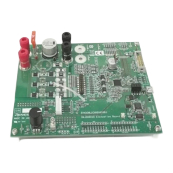
Page 16: Board
RAJ306010 RSSK(RTK0EML2C0S01020BJ) 2. Specification Overview Board 2.2.1. Main parts and terminals The main parts and terminals of the board are as follows: TB100 CN_LIGHT ,TB101 LED1-LED7 Q1-Q6 CN_ENC CN_INV CN_E1 USB1 ICS_SEL U,V,W CN_HALL AMP1 Figure 2-1. Main parts and terminals R18UZ0078EJ0100 Rev.1.0... - Page 17 RAJ306010 RSSK(RTK0EML2C0S01020BJ) 2. Specification Overview Table 2-2. Main parts list Parts number Item RAJ306010GNP (for motor control) RX231 (for ICS communication control) AMP1 Phase current detection amplifier (U-Phase, W-Phase) CN_E1 Emulator connector CN_ENC Encoder signal input connector CN_HALL HALL IC signal input connector...
-
Page 18: Spare_Circuit
RAJ306010 RSSK(RTK0EML2C0S01020BJ) 2. Specification Overview CN_SPI CN_I2C Spare_circuit CN_UART CN_VOL CN_DIGI CN_ANA Figure 2-2. Main parts and terminal (Non-mounted) R18UZ0078EJ0100 Rev.1.0 Page 8 Mar 24, 2021... - Page 19 UART communication connector CN_VOL External volume connector GND connection terminal 5V Power supply connection terminal (When using internal 5V regulator of RAJ306010, No need for external 5V power supply ) Power supply selection terminal for HALL-IC COMMON/Thermistor selection terminal 5V regulator selection terminal...
-
Page 20: Block Diagram
The board is initially written with a program that performs basic operations of 120° conduction control. its functional block diagram is shown in Figure 2-3. Also, the board has extended functions such as communication terminals and LED terminals. A block diagram of all the functions is shown in Figure 2-4. RAJ306010 Evaluation Board RAJ306010 (IC1) Hall-IC... - Page 21 (JP9) (ICS_SEL) Power LED (LED7) Isolation PE1(TxD12) 5V Input VREG5 VREG5 PE2(RxD12) RX231 Connector (IC2) Isolator Connector (ISO1) (J2,J1) P37,P36 (USB1) Colck (CT1) Power(VM) 5V(VREG5) Unmount 5V(USB) Figure 2-4. RAJ306010 Board Block diagram R18UZ0078EJ0100 Rev.1.0 Page 11 Mar 24, 2021...
-
Page 22: Motor [Tg-55L-Ka 24V(Tsukasa Electric Co.,Ltd)]
RAJ306010 RSSK(RTK0EML2C0S01020BJ) 2. Specification Overview 2.2.3. Motor [TG-55L-KA 24V(TSUKASA ELECTRIC CO.,LTD)] Refer to TSUKASA ELECTRIC website for the latest specifications. Table 2-4. TG-55L-KA 24V Motor specification Rated Voltage (V) Rated Speed (rpm) 2650 No-Load Speed (rpm) 3900 Rated Current (mA) No-Load Current (mA) Torque (mN·m) -
Page 23: Information
Address: Toyosu Foresia, 3-2-24, Toyosu, Koto-ku, Tokyo 135-0061, Japan Manufacturer ■ Product name: Renesas Solution Starter Kit Motor Control Evaluation System -Motor Control IC : RAJ306010 – Type name: RTK0EML2C0S01020BJ Environmental Compliance and Certifications: Waste Electrical and Electronic Equipment (WEEE) Directive 2012/19/EU ■... -
Page 24: How To Use
RAJ306010 RSSK(RTK0EML2C0S01020BJ) 3. How to use 3. How to use Quick start (Use the mounted MOSFET and attached motor) 3.1.1. Confirmation items before operation 1. Check the following 0Ω jumper settings. MOSFET selection resistors (R107-R124): Mounted right side ■ MOSFET thermistor selection resistor (R106): Mounted ■... - Page 25 RAJ306010 RSSK(RTK0EML2C0S01020BJ) 3. How to use Check the following connection and settings. Turn potentiometer VR1 counterclockwise to the end so that the motor does not rotate at the power on. ■ Connect the board and motor with motor connection cable ■...
-
Page 26: Error Release Method
RAJ306010 RSSK(RTK0EML2C0S01020BJ) 3. How to use Table 3-1. the initial firmware specification Contents Specification Rotate Speed 1200-3900[rpm] Control method Hall sensor 120° conduction control Clockwise: Rotation start → acceleration Counterclockwise: Deceleration → Stop rotation Top (1-2 short): Rotate clockwise Bottom (2-3 shorts): Turn counterclockwise... -
Page 27: Function
When using any motor, refer to "4.3.4" and supply the voltage according to the motor within the operating range of RAJ306010. (When using the motor included in this kit, supply 24V.) In addition, fuses are mounted on TB100 and TB101 of this board. Replace the fuse capacity according to the motor current to be controlled. -
Page 28: Update Firmware By Using Cs
RAJ306010 RSSK(RTK0EML2C0S01020BJ) 4. Function 4.2.1. Update firmware by using CS+ 1. Connect PC, emulator and board. Figure 4-1. E2 emulator connection 2. Supply power to the VM terminal select the download method from debug tab of CS+ tool. Recommended download method: Download to rebuild & debug tool. -
Page 29: Motor Driving Circuit
RAJ306010 RSSK(RTK0EML2C0S01020BJ) 4. Function Motor driving circuit On the board, a MOSFET, a shunt resistor, and a thermistor for MOSFET are mounted as motor driving circuit. Also, it is possible to connect an external motor drive circuit to CN_INV (external MOSFET connector). In order to switch the motor drive circuit, it is necessary to set by 0Ω... - Page 30 RAJ306010 RSSK(RTK0EML2C0S01020BJ) 4. Function Table 4-3. Pin assign of External MOSFET connector (CN_INV) Connector Pin No. Silk screen (Terminal function) RAJ306010 Pin CN_INV P21 (for thermistor analog input) P21/ANI11 GND (for thermistor GND) GND (for guard shield of ISENP/ISENN) GND (for guard shield of ISENP/ISENN)
-
Page 31: Mosfet
4.3.2. Shunt resistor Using the shunt current sense amplifier built in the RAJ306010, the power supply current is detected, and overcurrent protection is performed by measuring the voltage difference between the two ends of the shunt resistor connected to the ISENP/ISENN pin. A shunt resistor (R65: 100mΩ) is mounted on this board between the MOS_GND pin (J5) and the GND input pin (J6). -
Page 32: Mofet Thermistor (Option)
RAJ306010 RSSK(RTK0EML2C0S01020BJ) 4. Function 4.3.3. MOFET thermistor (Option) The thermistor(Z1) is mounted to measure MOSFET temperature. By default, the on-board thermistor (Z1) is available by mounted 0Ω register of the MOSFET thermistor selection resistor(R106) and the on-board thermistor (Z1) is connected to P21 (ANI1). -
Page 33: Connect User's Motor (Not Attached Motor)
Figure 4-6. Parts change location (Connect User’s motor) Attention! Renesas will not be liable for any damages such as board failure or injury resulting from the change. Please be safe to change and configure the board at your own risk. -
Page 34: Use External Mosfet Board
RAJ306010 RSSK(RTK0EML2C0S01020BJ) 4. Function 4.3.5. Use external MOSFET board 1. 0Ω jumper setting MOSFET connection selection resistors (R107-R124):Select left side (on-board MOSFET is off) ■ MOSFET thermistor selection resistor(R106): Open (Thermistor connected to CN_INV is valid) ■ Shunt resistor selection resistors (R102-R105): Select right side(on-board shunt resistor (R65) is ■... - Page 35 Select MOSFETs with a withstand voltage that takes into account the amplitude of the supply voltage. Attention! Renesas will not be liable for any damages such as board failure or injury resulting from the change. Please be safe to change and configure the board at your own risk.
-
Page 36: Potentiometer (Vr1) & Toggle Switch (Ts1)
RAJ306010 RSSK(RTK0EML2C0S01020BJ) 4. Function Potentiometer (VR1) & Toggle switch (TS1) A potentiometer is mounted and connected to ANI6 for input indication of the amount of rotation. The resistance of the potentiometer is 20kΩ and is pulled up to 5V by a resistance of 5.6kΩ and has hysteresis. -
Page 37: Uart Terminal
Table 4-7. UART connector (CN_UART, CN7) pin assignment Connector Terminal No. Silk screen(Terminal function) RAJ306010 terminal CN_UART TxD1(RAJ306010 UART Send) P02/TxD1 RxD1(RAJ306010 UART Receive) P03/RxD1 SPI Terminal For SPI communication, a through hole for CN_SPI connector and check through hole (CN5) are mounted on the board. -
Page 38: I2C Terminal
RAJ306010 RSSK(RTK0EML2C0S01020BJ) 4. Function I2C terminal For I2C communication, a through hole for CN_I2C connector and check through hole (CN6) are mounted on the board. The initial firmware does not use I2C terminal. Communication method: Normal mode, Fast mode, Fast mode plus ■... -
Page 39: Analog General Purpose I/O Terminal
RAJ306010 RSSK(RTK0EML2C0S01020BJ) 4. Function Analog general purpose I/O terminal For AD converter input and general purpose digital port terminal, a through hole for CN_ANA connector and check through hole (CN2) are mounted on the board. The pin assignment of CN_ANA is shown below. -
Page 40: Hall Ic Input Terminal
JP3. Pins No.3-No.5 are used to input Hall IC signals. The input Hall signals are input to the RAJ306010 via a pull-up with 5V and an RC filter. Please refer to the circuit diagram for the filter constants. -
Page 41: Encoder Signal Input
Note1 When performing operations such as vector control, input the motor encoder signal from this connector to the RAJ306010. Both VCC and VDD are 5V(same voltage). The pin assignment of CN_ENC connector are shown below. Note.1 : When using the CN_ENC connecter, remove R56 and R57. LED1 and LED2 can not be used. -
Page 42: Phase Current Detection Amplifier
RAJ306010 RSSK(RTK0EML2C0S01020BJ) 4. Function 4.12 Phase current detection Amplifier Amplifiers are mounted on the U and W phases to detect the current that drives the motor on the board. In the initial state, this amplifier is invalid. If this amplifier is required, such as encoder vector control, mount the following resistors and disconnect the resistors. -
Page 43: Led
RAJ306010 RSSK(RTK0EML2C0S01020BJ) 4. Function 4.13 LED Seven LEDs are mounted for program debugging and system operation confirmation. Lights when the terminal level is low and turns off when the terminal level is high. The pin assignments corresponding to the LEDs are shown below. -
Page 44: High Brightness Led Terminal
RAJ306010 RSSK(RTK0EML2C0S01020BJ) 4. Function 4.14 High Brightness LED terminal This product has connector CN_LIGHT corresponding to large current drive such as LED light and the through hole CN10 for checking. Please note that the voltage of this terminal is VM level. -
Page 45: Power Supply Current Check Terminal
4. Function 4.15 Power supply current check terminal For measuring the current of RAJ306010, through holes for VM current measurement (JP8: not mounted) and through holes for VDD current measurement (JP9) are mounted on the board. When using these terminals, remove the 0Ω... -
Page 46: Spare_Circuit
RAJ306010 RSSK(RTK0EML2C0S01020BJ) 4. Function 4.17 Spare_circuit This circuit is a spare circuit. Therefore, no components are mounted, and VDD_in/VSS_in are independent from other circuits. Please use it by connecting it to peripheral circuits as needed. In this board, TPH2R506PL,L1Q MOSFETs are mounted to support applications that require high torque, but ringing tends to appear in the BEMF waveform when used with the included motor. -
Page 47: Ics (Wave Viewer Tool) Host Function
ICS Library programing method: “ICS++ RL78 Lib for CS+/EWRL manual V3.7x download” ■ This tool or library is a sample and is free or unsupported. In addition, Renesas can not be held responsible for any problems such as damage caused by incorporating or using this tool. -
Page 48: Raj306010
RAJ306010 RSSK(RTK0EML2C0S01020BJ) 5. RAJ306010 5. RAJ306010 Feature RAJ306010 is a SIP built in RL78/G1F and Pre-Driver. The main features are described below. For details, refer to the data sheet and Hardware Manual. RL78/G1F (R5F11BLEGFB) ■ Flash ROM: 64KB ● Data Flash: 4KB ●... -
Page 49: Raj306010 Pin Assignment
Exposed Tab RESET WHOUT (e-PAD) P137/INTP0 P122/EXCLK WLOUT REGC DrvGND1 e-PAD is connected P60/SCLA0 with AGND1,2. P61/SDAA0 Figure 5-1. RAJ306010 Pin assignment Note: Bold text : RL78 pins Normal-face font : Pre-driver pins R18UZ0078EJ0100 Rev.1.0 Page 39 Mar 24, 2021... -
Page 50: Raj306010 Pin Function List
RAJ306010 RSSK(RTK0EML2C0S01020BJ) 5. RAJ306010 5.2.1. RAJ306010 Pin function list Table 5-1. RAJ306010 Pin function list (1/3) Pin No. RAJ306010 Pin function Connector/TP/Function Note P01/TO00/TRGCLKB/(INTP10) LED1/CN_ENC-3 Pin When using CN_ENC, CN8-3 Pin disconnect R56 resistor. P00/TI00/TRGCLKA/TRJO0/(INTP8) LED2/CN_ENC-4 Pin When using CN_ENC, CN8-4 Pin disconnect R57 resistor. - Page 51 RAJ306010 RSSK(RTK0EML2C0S01020BJ) 5. RAJ306010 Table 5-2. . RAJ306010 Pin function list (2/3) VREG5 VREG5_SEL 5V input/output selection AGND1 Connect to GND with 0Ω resistor. Capacitor connection terminal for charge pump Capacitor connection terminal for charge pump TH11 Connect to GND with 0Ω...
- Page 52 CN_UART-2 Pin/ CN7-2 Pin Note. Unused general-purpose pins of RAJ306010 have unimplemented pins such as pull-up and pull-down resistors on the board for functional expansion. After confirming the recommended pin settings described in the circuit diagram of this board and the user's manual hardware of the RAJ306010, process correctly with the user program or hardware.
- Page 53 Revision History RAJ306000 Series User’s Manual: RSSK Rev. Date Description Page Summary 1.00 Mar.24.21 First Edition issued C - 1...
- Page 54 RAJ306000 Series User’s Manual: RSSK Publication Date: Rev.1.00 Mar.24.21 Published by: Renesas Electronics Corporation...
- Page 55 Renesas' products are provided only subject to Renesas' Terms and Conditions of Sale or other applicable terms agreed to in writing. No use of any Renesas resources expands or otherwise alters any applicable warranties or warranty disclaimers for these products.
- Page 56 RAJ306000 Series R18UZ0078EJ0100...
Need help?
Do you have a question about the RAJ306010 and is the answer not in the manual?
Questions and answers