Table of Contents
Advertisement
Quick Links
RA6T2 Group
Renesas RA Family
RA6 Series
All information contained in these materials, including products and product specifications,
represents information on the product at the time of publication and is subject to change by
Renesas Electronics Corp. without notice. Please review the latest information published by
Renesas Electronics Corp. through various means, including the Renesas Electronics Corp.
website (http://www.renesas.com).
www.renesas.com
MCB-RA6T2 User's Manual
Rev. 1.10 March 31, 2022
Advertisement
Table of Contents

Related Manuals for Renesas MCB-RA6T2


Summary of Contents for Renesas MCB-RA6T2
- Page 1 All information contained in these materials, including products and product specifications, represents information on the product at the time of publication and is subject to change by Renesas Electronics Corp. without notice. Please review the latest information published by Renesas Electronics Corp. through various means, including the Renesas Electronics Corp.
- Page 2 Renesas Electronics disclaims any and all liability for any damages or losses incurred by you or any third parties arising from the use of any Renesas Electronics product that is inconsistent with any Renesas Electronics data sheet, user’s manual or other Renesas Electronics document.
- Page 3 Unit Products The following usage notes are applicable to all Microprocessing unit and Microcontroller unit products from Renesas. For detailed usage notes on the products covered by this document, refer to the relevant sections of the document as well as any technical updates that have been issued for the products.
-
Page 4: Table Of Contents
User’s Manual Renesas RA Family MCB-RA6T2 User's Manual Contents Overview ..........................3 Presupposition and precautions of this document .................. 3 Product Contents ........................4 Product Order Information ....................... 4 Hardware Configuration and Default Setting ................5 Hardware configuration ........................... 5 Block diagram ............................ - Page 5 Renesas RA Family MCB-RA6T2 User's Manual Figure of contents Figure 2-1 Product contents ..........................4 Figure 4-1 Block Diagram of CPU Board ......................6 Figure 4-2 CPU Board Layout ........................... 7 Figure 4-3 Standoffs and Screws assembly ...................... 7 Figure 4-4 Default jumper pin setting ........................ 9 Figure 4-5 Connection Example ........................
-
Page 6: Overview
Renesas RA Family MCB-RA6T2 User's Manual 1. Overview MCB-RA6T2 is a CPU board for motor control evaluation. By using this product in combination with an inverter board, motor control using RA6T2 can be easily performed. 1.1 Presupposition and precautions of this document 1. -
Page 7: Product Contents
1. CPU Board (RTK0EMA270C00000BJ) x1 2. USB Cable x1 3. Screw x4 4. Standoff x4 Figure 2-1 Product contents 3. Product Order Information Product No. to order MCB-RA6T2 : RTK0EMA270C00000BJ R12UZ0099EJ0110 Rev 1.10 Page 4 of 18 March 31, 2022... -
Page 8: Hardware Configuration And Default Setting
Connector Inverter board connector (2 sets) USB connector for J-Link OB SCI connector for Renesas Motor Workbench communication Through hole for CAN communication Through hole for SPI communication 20 pin through hole for Arm debugger... -
Page 9: Block Diagram
Renesas RA Family MCB-RA6T2 User's Manual 4.2 Block diagram Figure 4-1 Block Diagram of CPU Board R12UZ0099EJ0110 Rev 1.10 Page 6 of 18 March 31, 2022... -
Page 10: Board Layout
Renesas RA Family MCB-RA6T2 User's Manual 4.3 Board Layout Figure 4-2 CPU Board Layout 4.4 Standoffs and Screws Before using this product, assemble the included standoffs and screws as shown below. Figure 4-3 Standoffs and Screws assembly R12UZ0099EJ0110 Rev 1.10... -
Page 11: Jumper Pin Setting
Renesas RA Family MCB-RA6T2 User's Manual 4.5 Jumper pin setting Default settings and functions of the jumper pins (JP1~JP25) are as follows. Table 4-2 Jumper pin setting Jumper pin Default setting Function 1-2pin short : INV1 IPS CSNIRQN 2-3pin short... -
Page 12: Connection Example
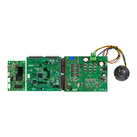
MCB-RA6T2 User's Manual Figure 4-4 Default jumper pin setting 4.6 Connection Example Figure 4-5 shows a connection example when using this product in combination with a Renesas inverter board kit (MCI-LV-1, P/N: RTK0EM0000S04020BJ) and a communication board (MC-COM, P/N: RTK0EMXC90S00000BJ). -
Page 13: Cpu Board Specification
Renesas RA Family MCB-RA6T2 User's Manual 5. CPU Board Specification This section describes the specification of the CPU Board. Functions 5.1.1 Power supply When not connected to the inverter board, power should be supplied from the USB connector. When connecting to the inverter board, power supply from the USB connector or from the inverter board will be automatically selected. - Page 14 Renesas RA Family MCB-RA6T2 User's Manual Table 5-2 1st Inverter board connector (CN5) pin assignment Pin No Pin Function RA6T2 Pin Pin No Pin Function RA6T2 Pin PB09/GTIOC6B_B - (VSS) PB08/GTIOC6A_B - (VSS) SPARE2 SPARE3 SPARE4 SPARE5 BUS_POWER_IN INV_CONNECTED SAFE_LOCK...
-
Page 15: Serial Communication
Figure 5-1 Connection for CPU board and inverter board 5.1.4 Serial communication For serial communication using Renesas Motor Workbench, the CPU board has SCI connector. Pin assignment for SCI connector is listed in Table 5-5. Table 5-5 SCI connector (CN10) pin assignment Pin No. -
Page 16: Led
Renesas RA Family MCB-RA6T2 User's Manual 5.1.6 This product has six ports and LEDs, so that they can be used for program debug and the system. LED switches on when output from the corresponding port is “LOW” and switches off when output is “HIGH”. Pin assignment for corresponding LEDs is listed in Table 5-6. -
Page 17: Ra6T2 Pin Function List
Renesas RA Family MCB-RA6T2 User's Manual 5.2 RA6T2 pin function list Table 5-9 RA6T2 pin function list Pin number RA6T2 pin function Signal function PE02/TRCLK/CMPOUT0_C/GTOVLO_C/GTIOC7B_B/GTIOC8A_E/GT ARM debugger CPPO8/SCK0_B/DE0_D/SCK3_A/DE3_A/RSPCKB_C/CLKOUT_C PE03/TRDATA0/CMPOUT1_C/GTOWLO_C/GTIOC8A_B/GTIOC9A_E/ ARM debugger GTCPPO6/RXD0_B/CTS3_A/SSLB0_C/GTODFMA PE04/TRDATA1/CMPOUT2_C/GTOUUP_C/GTIOC8B_B/GTIOC7B_E/ ARM debugger GTCPPO9/TXD0_B/SS_CTS_RTS3_A/DE3_A/SSLB1_C/GTODFMB PE05/TRDATA2/CMPOUT3_C/GTOVUP_C/GTIOC9A_B/GTIOC8B_E/ ARM debugger GTCPPO2/SS_CTS_RTS0_B/DE0_B/RXD3_A/MISOB_C/GTODFMC... - Page 18 Renesas RA Family MCB-RA6T2 User's Manual Pin number RA6T2 pin function Signal function PB02/AN018 (AN118)/PGAIN3/IVCMP32 / IVCMP33/IRQ15DS INV2 U-phase current detection P002/AN019 (AN119)/PGAVSS3 INV2 PGAVSS_U PE08/AN020/AN120/ADTRG0_E/CMPOUT012_C/GTIV_B/GTIOC3A_ INV2 V-phase current B/GTETRGC/GTADSM0/SSLA3_C/KR00_E/GTODFMON detection PE09/AN021/AN121/ADTRG1_E/CMPOUT345_C/GTIW_B/GTIOC3B_ INV2 W-phase current B/GTETRGD/GTADSM1/CACREF_F/SSLA2_C/KR01_E detection PE10/AN022/AN122/GTOULO_B/GTIOC2A_B/GTIOC4A_C/GTIOC7A INV2 U-phase voltage...
- Page 19 Renesas RA Family MCB-RA6T2 User's Manual Pin number RA6T2 pin function Signal function _C/GTIOC8B_F/RXD0_A/SDA1_C/RSPCKA_B/KR02_B/IRQ10_A (Upper) PA11/CMPOUT1_A/GTETRGD/GTIOC9B_A/GTETRGC/GTIOC3B_C/ INV2 PWM W-phase CTX0_A/CTS0_A/RXD1_C/MOSIA_B/KR03_B/IRQ11_A (Lower) PA12/ADTRG1_A/GTETRGB/GTCPPO0/GTCPPO2/GTADSM0/GTCP INV2 over current PO7/CACREF_A/CRX0_A/SS_CTS_RTS0_A/DE0_A/TXD1_C/MISOA detection/PFC over _B/KR04_B/IRQ12_A/GTODFMA current detection PA13/TMS/SWDIO/TMS/SWDIO/AGTWO0_A/SCK0_C/DE0_C/SS_CT ARM debugger S_RTS1_C/DE1_C VCL2 Power Power Power PA14/TCK/SWCLK/AGTWO1_A/TXD0_C/SCK9_B/DE9_B...
-
Page 20: Design And Manufacture Information
MCB-RA6T2 User's Manual 6. Design and Manufacture Information You can obtain information on the design and manufacture of this product from renesas.com. 7. Website and Support In order to learn, download tools and documents, apply technical support for RA family MCU and its kit, visit the below Web site. - Page 21 Renesas RA Family MCB-RA6T2 User's Manual Revision History MCB-RA6T2 User's Manual Rev. Date Description Page Summary 1.00 August 3, 2021 First edition 1.10 March 31, 2022 Modified Table 5-5 R12UZ0099EJ0110 Rev 1.10 Page 18 of 18 March 31, 2022...
- Page 22 MCB-RA6T2 User's Manual Publication Date: Rev 1.10 March 31, 2022 Published by: Renesas Electronics Corporation...
- Page 23 MCK-RA6T2 User's Manual R12UZ0099EJ0110...
- Page 24 Mouser Electronics Authorized Distributor Click to View Pricing, Inventory, Delivery & Lifecycle Information: Renesas Electronics RTK0EMA270C00000BJ...
Need help?
Do you have a question about the MCB-RA6T2 and is the answer not in the manual?
Questions and answers