Table of Contents
Advertisement
Quick Links
UG512: BB52 Explorer Kit User's Guide
The BB52 Explorer Kit is an ultra-low cost, small form factor devel-
opment and evaluation platform for the EFM8BB52 Busy Bee 8-bit
microcontroller.
The BB52 Explorer Kit is focused on rapid prototyping and concept creation of multi-pur-
pose applications. It is designed around the EFM8BB52 MCU, which is an ideal device
family for developing energy-friendly embedded applications.
The kit features a USB interface, an on-board SEGGER J-Link debugger, one user-LED
and button, and support for hardware add-on boards via a mikroBUS™ socket and a
Qwiic® connector. The hardware add-on support allows developers to create and proto-
type applications using a virtually endless combination of off-the-shelf boards from mik-
roE, sparkfun, AdaFruit, and Seeed Studios.
silabs.com | Building a more connected world.
Copyright © 2021 by Silicon Laboratories
TARGET DEVICE
• EFM8BB52 Busy Bee 8-bit microcontroller
(EFM8BB52F32I-C-QFN32R)
• Pipelined 8-bit C8051 core with 50 MHz
maximum operating frequency
• 32 kB flash and 2304 bytes RAM
KIT FEATURES
• User LED and push button
• 2.54 mm breakout pads
• mikroBUS™ socket
• Qwiic® connector
• SEGGER J-Link on-board debugger
• Virtual COM port
• USB-powered
SOFTWARE SUPPORT
• Simplicity Studio™
ORDERING INFORMATION
• BB52-EK2701A
Rev. 1.0
Advertisement
Table of Contents

Related Manuals for Silicon Laboratories BB52 Explorer Kit


Summary of Contents for Silicon Laboratories BB52 Explorer Kit
- Page 1 • EFM8BB52 Busy Bee 8-bit microcontroller (EFM8BB52F32I-C-QFN32R) The BB52 Explorer Kit is focused on rapid prototyping and concept creation of multi-pur- • Pipelined 8-bit C8051 core with 50 MHz pose applications. It is designed around the EFM8BB52 MCU, which is an ideal device maximum operating frequency family for developing energy-friendly embedded applications.
-
Page 2: Table Of Contents
Table of Contents 1. Introduction ....... . 3 1.1 Kit Contents ....... 3 1.2 Getting Started . -
Page 3: Introduction
Programming the BB52 Explorer Kit is easily done using a USB Micro-B cable and the on-board J-Link debugger. A USB virtual COM port provides a serial connection to the target application. The BB52 Explorer Kit is supported in Simplicity Studio™ and a Board Sup- port Package (BSP) is provided to give application developers a flying start. -
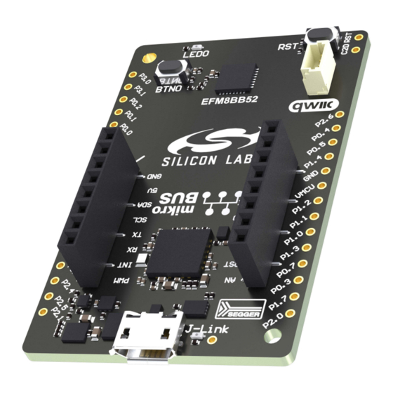
Page 4: Kit Hardware Layout
UG512: BB52 Explorer Kit User's Guide Introduction 1.4 Kit Hardware Layout The layout of the BB52 Explorer Kit is shown below. 35.6 mm EFM8BB52 Top View Reset Button Push Button Qwiic Connector Breakout Pads 55.9 mm On-board USB J-Link Debugger... -
Page 5: Specifications
UG512: BB52 Explorer Kit User's Guide Specifications 2. Specifications 2.1 Recommended Operating Conditions Parameter Symbol Unit USB Supply Input Voltage 1 , 2 Supply Input Voltage (VMCU supplied externally) VMCU Operating Temperature ˚C Not recommended for use with rechargeable Lithium batteries. Most Li-Ion and Li-Po cells exceed 3.6 V when fully charged When using the provided interfaces with add-on boards or other external hardware, tighter voltage limits might apply 2.2 Current Consumption... -
Page 6: Hardware
UG512: BB52 Explorer Kit User's Guide Hardware 3. Hardware The core of the BB52 Explorer Kit is the EFM8BB52 Busy Bee 8-bit microcontroller. Refer to section 1.4 Kit Hardware Layout for place- ment and layout of the hardware components. 3.1 Block Diagram An overview of the BB52 Explorer Kit is illustrated in the figure below. -
Page 7: Power Supply
8-bit MCU Peripherals Figure 3.2. BB52 Explorer Kit Power Topology The 5 volt power net on the USB bus is regulated down to 3.3 V using an LDO (low-dropout regulator). An automatic isolation circuit isolates the LDO when the USB cable is not plugged in. -
Page 8: On-Board Debugger
3.5 On-board Debugger The BB52 Explorer Kit contains a microcontroller separate from the EFM8BB52 Busy Bee that provides the user with an on-board J- Link debugger through the USB Micro-B port. This microcontroller is referred to as the "on-board debugger", and is not programmable by the user. -
Page 9: Breakout Pads
The pin-routing on the Busy Bee is flexible, so most peripherals can be routed to any pin on port 1 or 2. However, pins may be shared between the breakout pads and other functions on the BB52 Explorer Kit. The figure in section 3.6 Connectors... -
Page 10: Mikrobus Socket
Qwiic connector, and all mikroBUS signals are also routed to adjacent breakout pads. When inserting a mikroBUS add-on board, refer to the orientation notch on the BB52 Explorer Kit, shown in the figure below, to ensure correct orientation. -
Page 11: Qwiic Connector
The BB52 Explorer Kit features a Qwiic® connector compatible with Qwiic Connect System hardware. The Qwiic connector provides an easy way to expand the functionality of the BB52 Explorer Kit with sensors, LCDs, and other peripherals over the I C interface. The Qwiic connector is a 4-pin polarized JST connector, which ensures the cable is inserted the right way. -
Page 12: Debugging
4. Debugging The BB52 Explorer Kit contains an on-board SEGGER J-Link Debugger that is connected to the C2 debugging interface on the EFM8BB52. The debugger allows the user to download code and debug applications running in the target EFM8BB52. Additionally, it also provides a virtual COM port (VCOM) to the host computer that is connected to the target device's serial port, for general purpose communication between the running application and the host computer. -
Page 13: Schematics, Assembly Drawings, And Bom
UG512: BB52 Explorer Kit User's Guide Schematics, Assembly Drawings, and BOM 5. Schematics, Assembly Drawings, and BOM Schematics, assembly drawings, and bill of materials (BOM) are available through Simplicity Studio when the kit documentation pack- age has been installed. They are also available from the kit page on the Silicon Labs website: http://www.silabs.com/. -
Page 14: Kit Revision History
UG512: BB52 Explorer Kit User's Guide Kit Revision History 6. Kit Revision History The kit revision can be found printed on the box label of the kit, as outlined in the figure below. The kit revision history is summarized in the table below. -
Page 15: Board Revision History And Errata
UG512: BB52 Explorer Kit User's Guide Board Revision History and Errata 7. Board Revision History and Errata 7.1 Revision History The board revision can be found laser printed on the board, and the board revision history is summarized in the following table. - Page 16 Note: This content may contain offensive terminology that is now obsolete. Silicon Labs is replacing these terms with inclusive language wherever possible. For more information, visit www.silabs.com/about-us/inclusive-lexicon-project Trademark Information Silicon Laboratories Inc. , Silicon Laboratories , Silicon Labs , SiLabs...
Need help?
Do you have a question about the BB52 Explorer Kit and is the answer not in the manual?
Questions and answers