Table of Contents
Advertisement
Quick Links
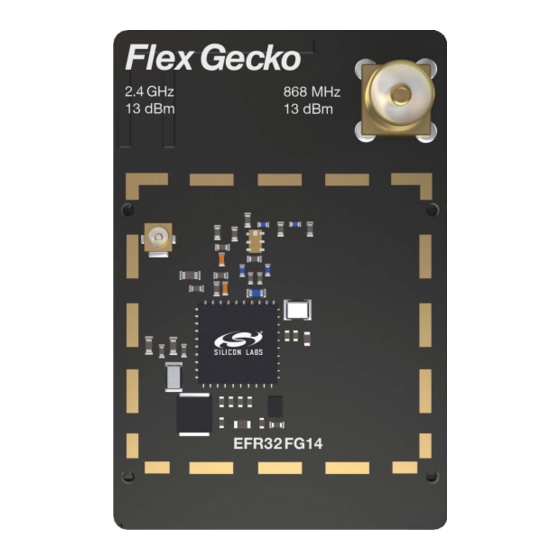
EFR32FG14 2400/868 MHz Dual Band
13 dBm Radio Board
BRD4257B Reference Manual
The BRD4257B Flex Gecko Radio Board enables developers to develop proprietary
wireless applications. The board contains a dual-band Flex Gecko Wireless System-on-
Chip and it is optimized for operating at 13 dBm output power. For the 2.4 GHz band
with the on-board printed antenna and UFL connector, radiated and conducted testing is
supported. For the 868 MHz band, the on-board SMA connector enables conducted
testing and attachment of external whip antenna for radiated tests.
The BRD4257B Flex Gecko Radio Board plugs into the Wireless Starter Kit Mainboard,
which is included with the Flex Gecko Starter Kit and gives access to display, buttons
and additional features from Expansion Boards. With the supporting Simplicity Studio
suite of tools, developers can take advantage of graphical wireless application develop-
ment and visual energy profiling and optimization. The board also serves as an RF ref-
erence design for applications targeting 2.4 GHz and 868 MHz dual band wireless oper-
ation with 13 dBm output power.
This document contains a brief introduction and description of the BRD4257B Radio
Board features, focusing on the RF sections and performance.
silabs.com | Building a more connected world.
RADIO BOARD FEATURES
• Wireless SoC:
EFR32FG14P233F256GM48
• CPU core: ARM Cortex
®
-M4 with FPU
• Flash memory: 256 kB
• RAM: 32 kB
• Operation frequency: 2.4 GHz + 868 MHz
• Transmit power: 13 dBm
• 2.4 GHz: Integrated PCB antenna, UFL
connector (optional)
• 868 MHz: Single SMA connector both for
transmit and receive
• Crystals for LFXO and HFXO: 32.768 kHz
and 38.4 MHz
• 8 Mbit low-power serial flash for over-the-
air updates
Rev. 1.00
Advertisement
Table of Contents

Related Manuals for Silicon Laboratories BRD4257B


Summary of Contents for Silicon Laboratories BRD4257B
- Page 1 -M4 with FPU • Flash memory: 256 kB The BRD4257B Flex Gecko Radio Board plugs into the Wireless Starter Kit Mainboard, • RAM: 32 kB which is included with the Flex Gecko Starter Kit and gives access to display, buttons •...
-
Page 2: Table Of Contents
Table of Contents 1. Introduction ....... . 4 2. Radio Board Connector ......5 2.1 Introduction. - Page 3 7.1.1 Conducted Measurements in the 868 MHz Band ....14 7.1.2 Conducted Measurements in the 2.4 GHz Band ....15 7.2 Radiated Power Measurements .
-
Page 4: Introduction
13 dBm output power. To develop and/or evaluate the EFR32 Flex Gecko, the BRD4257B Radio Board can be connected to the Wireless Starter Kit Main- board to get access to display, buttons and additional features from Expansion Boards and also to evaluate the performance of the RF interfaces. -
Page 5: Radio Board Connector
P33 / PD14 / DISP_SCS USB_VBUS USB_VREG NC / P34 P35 / PD15 / DISP_ENABLE / SENSOR_ENABLE VRF_IN Board ID SCL Board ID SDA Figure 2.1. BRD4257B Radio Board Connector Pin Mapping silabs.com | Building a more connected world. Rev. 1.00 | 5... -
Page 6: Radio Board Block Summary
The BRD4257B Radio Board has a 32.768 kHz crystal mounted. For details regarding the crystal configuration, refer to Application Note "AN0016: Oscillator Design Considerations". 3.3.3 HF Crystal Oscillator (HFXO) The BRD4257B Radio Board has a 38.4 MHz crystal mounted. For details regarding the crystal configuration, refer to Application Note "AN0016: Oscillator Design Considerations". 3.3.4 Matching Network for Sub-GHz The BRD4257B Radio Board incorporates a sub-GHz matching network which connects both the sub-GHz TX and RX pins of the EFR32FG14 to the SMA connector to be able to transmit and receive with one antenna. -
Page 7: Matching Network For 2.4 Ghz
3.3.5 Matching Network for 2.4 GHz The BRD4257B Radio Board incorporates a 2.4 GHz matching network which connects the 2.4 GHz TRX pin of the EFR32FG14 to the one on-board printed inverted-F antenna. The component values have been optimized for the 2.4 GHz band RF performance and cur- rent consumption with 13 dBm output power. -
Page 8: Rf Section
4.3 RF Section Power Supply On the BRD4257B Radio Board the supply for the radio (RFVDD) and the sub-GHz and 2.4 GHz power amplifiers (SUBGRF_ON, SUBGRF_OP and PAVDD pins) is connected to the on-chip DC-DC converter. This way, by default, the DC-DC converter provides 1.8 V for the entire RF section (for details, see the schematic of the BRD4257B). -
Page 9: Bill Of Materials For The 2.4 Ghz Matching
4.5 Bill of Materials for the 2.4 GHz Matching The Bill of Materials of the 2.4 GHz matching network of the BRD4257B Radio Board is shown in the following table. Table 4.2. Bill of Materials for the BRD4257B 2.4GHz RF Matching Network... - Page 10 BRD4257B Reference Manual RF Section Figure 4.2. Impedance and Reflection of the Inverted-F Antenna of the BRD4257B Board Measured from the Matching Output silabs.com | Building a more connected world. Rev. 1.00 | 10...
-
Page 11: Mechanical Details
BRD4257B Reference Manual Mechanical Details 5. Mechanical Details The BRD4257B Radio Board is illustrated in the figures below. 2.4 GHz Matching Connector and Filter DC-DC LFXTAL Inductor DC-DC 2.4 GHz Path & Selection Supply EFR32xx Filter Sub-GHz Printed Caps. Matching... -
Page 12: Emc Compliance
BRD4257B Reference Manual EMC Compliance 6. EMC Compliance 6.1 Introduction Compliance of the fundamental and harmonic levels of the BRD4257B Radio Board is tested against the following standards: • 868 MHz: • ETSI EN 300-220-1 • 2.4 GHz: • ETSI EN 300-328 •... -
Page 13: Applied Emission Limits For The 2.4 Ghz Band
BRD4257B Reference Manual EMC Compliance 6.5 Applied Emission Limits for the 2.4 GHz Band The above ETSI limits are applied both for conducted and radiated measurements. The FCC restricted band limits are radiated limits only. In addition, Silicon Labs applies the same restrictions to the conducted spec- trum. -
Page 14: Rf Performance
7.1.1 Conducted Measurements in the 868 MHz Band The BRD4257B Radio Board was connected directly to a Spectrum Analyzer through its SMA connector. The supply for the RF section (RFVDD) and the sub-GHz power amplifier (SUBGRF_ON, SUBGRF_OP) was 1.8 V provided by the on-chip DCDC converter (for the sub-GHz PA it was provided as VBIAS through the discrete balun);... -
Page 15: Conducted Measurements In The 2.4 Ghz Band
0 Ohm resistor was soldered to the R2 resistor position). The supply for the RF section (RFVDD) and the 2.4 GHz power amplifi- er (PAVDD) was 1.8 V provided by the on-chip DC-DC converter; for details, see the schematic of the BRD4257B. The transceiver was operated in continuous carrier transmission mode. -
Page 16: Radiated Power Measurements
7.2 Radiated Power Measurements During measurements, the BRD4257B Radio Board was attached to a Wireless Starter Kit Mainboard which was supplied by USB. The voltage supply for the Radio Board was 3.3 V. The radiated power was measured in an antenna chamber by rotating the board 360 de- grees with horizontal and vertical reference antenna polarizations in the XY, XZ and YZ cuts. -
Page 17: Radiated Measurements In The 868 Mhz Band
For the 868 MHz radiated power measurements, an external whip antenna (P/N: ANT-868-CW-HWR-SMA) was used as a transmitter antenna. It was connected to the SMA connector of the BRD4257B Radio Board. The supply for the RF section (RFVDD) and the sub- GHz power amplifier (SUBGRF_ON, SUBGRF_OP) was 1.8 V provided by the on-chip DCDC converter (for the sub-GHz PA it was... -
Page 18: Emc Compliance Recommendations
8.1 Recommendations for 868 MHz ETSI EN 300-220-1 Compliance As it was shown in the previous chapter, the BRD4257B Flex Gecko Radio Board with 13 dBm output power is compliant with the emis- sion limits of the ETSI EN 300-220-1 regulation. Although the BRD4257B Radio Board has an option for mounting a shielding can, it is not required for the compliance. -
Page 19: Board Revision History
BRD4257B Reference Manual Board Revision History 9. Board Revision History Table 9.1. BRD4257B Radio Board Revisions Radio Board Revision Description Updating EFR revision to Rev. B. Initial revision. Note: The silkscreen marking on the board (e.g. PCBxxxx A00) denotes the revision of the PCB. The revision of the actual Radio Board is laser printed in the 'Board Info' field on the PCB. -
Page 20: Errata
BRD4257B Reference Manual Errata 10. Errata There are no known errata at present. silabs.com | Building a more connected world. Rev. 1.00 | 20... -
Page 21: Document Revision History
BRD4257B Reference Manual Document Revision History 11. Document Revision History Revision 1.00 2017-10-26 Initial document revision. silabs.com | Building a more connected world. Rev. 1.00 | 21... - Page 22 Trademark Information Silicon Laboratories Inc.® , Silicon Laboratories®, Silicon Labs®, SiLabs® and the Silicon Labs logo®, Bluegiga®, Bluegiga Logo®, Clockbuilder®, CMEMS®, DSPLL®, EFM®, EFM32®, EFR, Ember®, Energy Micro, Energy Micro logo and combinations thereof, "the world’s most energy friendly microcontrollers", Ember®, EZLink®, EZRadio®, EZRadioPRO®, Gecko®, ISOmodem®, Micrium, Precision32®, ProSLIC®, Simplicity Studio®, SiPHY®, Telegesis, the Telegesis Logo®, USBXpress®, Zentri and others are trademarks or registered...
Need help?
Do you have a question about the BRD4257B and is the answer not in the manual?
Questions and answers