Table of Contents
Advertisement
Quick Links
C 8 05 1F 4 11 E
1. Kit Contents
The C8051F411 Evaluation Kit contains the following items:
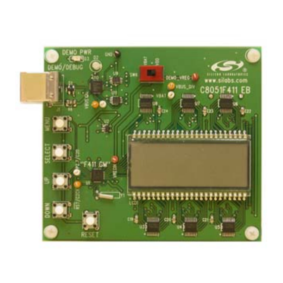
C8051F411 Evaluation Board
Silicon Laboratories Evaluation Kit IDE and Product Information
CD-ROM. CD contents include:
Silicon Laboratories Integrated Development Environment (IDE)
Source code examples and register definition files
Documentation
C8051F411 demo object code
6' USB Cable
2 AAA Batteries
C8051F411 Evaluation Kit Quick Start Guide
2. Kit Overview
The C8051F411 Evaluation Kit demonstrates some of the unique features of the C8051F41x family:
High-performance 8051 Core – Up to 50 MIPS with a 50 MHz system clock derived from the internal oscillator
and clock multiplier.
Low-voltage Operation – Can operate on a core supply voltage as low as 2.0 V.
Versatile Interfacing – Includes an internal voltage regulator that can supply up to 50 mA at 2.5 V or 2.1 V
output.
Real Time Clock – Can accurately maintain time for up to 137 years as long as the RTC peripheral is powered
by at least 1.0 V, even if the MCU core supply voltage is lost.
The C8051F411 Evaluation Board includes a USB interface that allows debugging with the Silicon Laboratories
IDE. Power for the C8051F411 board can be supplied from the batteries or the USB connection. Refer to "3.
Evaluation Board Interface" for more details.
3. Evaluation Board Interface
The user interface of the C8051F411 Evaluation Board includes an LCD and four push-buttons. There is also a
USB port for debugging and downloading to the C8051F411 target device.
3.1. LCD User Interface
The C8051F411 Evaluation Board user interface consists of an LCD screen, four buttons, and a switch. The LCD
screen displays menu choices and information to the user. The four push buttons, MENU, SELECT, UP, and
DOWN, are used to navigate the menus and make selections. The switch determines the power source for the
C8051F411 and can be used to switch between the batteries (the left position) and the USB bus (the right position).
The C8051F411 Block Diagram shown in Figure 1 shows all elements of the user interface.
When the board is powered but idle, the LCD screen will display the time in the upper left corner and cycle through
different sets of information, depending upon the operating mode of the board. Refer to "4. Evaluation Modes" for
more details on the operating modes.
The MENU button brings up the menu on the LCD display. When navigating through the menu options, pressing
this button will revert back to the beginning of the menu, and none of the changes will be saved. The menu
interface is described in "4. Evaluation Modes".
Rev. 0.1 2/06
K
V A L U A T I O N
Copyright © 2006 by Silicon Laboratories
C 8 0 5 1 F 4 11 - E K
U
'
G
IT
SER
S
U I D E
C8051F411-EK
Advertisement
Table of Contents

Related Manuals for Silicon Laboratories C8051F411


Summary of Contents for Silicon Laboratories C8051F411
-
Page 1: Kit Contents
DOWN, are used to navigate the menus and make selections. The switch determines the power source for the C8051F411 and can be used to switch between the batteries (the left position) and the USB bus (the right position). The C8051F411 Block Diagram shown in Figure 1 shows all elements of the user interface. -
Page 2: Evaluation Modes
These buttons also have special functionality depending upon the current mode. 3.2. Reset Button and LEDs The remaining push button is connected to the RESET pin of the C8051F411. Pressing this button puts the device into its hardware-reset state. Two LEDs are also provided on the evaluation board: ... - Page 3 C8051F411-EK KEEPSAKE Mode Time Time Temperature / Date Temperature Time Time DOWN DOWN (24 hr) (12 hr) Temperature / Date Temperature / Date Figure 2. Keepsake Mode Display Options The time, date, and temperature can be set and calibrated while in Keepsake mode. To do so, press the MENU button, and use the UP and DOWN buttons to cycle through the options.
- Page 4 C8051F411-EK MENU Mode 12/24 HR FAH-CEL TEMP DATE DEMO TIME DOWN DOWN DOWN DOWN DOWN DOWN DOWN SELECT SELECT SELECT SELECT SELECT SELECT 12 HOUR / CELSIUS / 25 deg C Y 2000 H 00 See Figure 4 24 HOUR...
-
Page 5: Demo Mode
C8051F411-EK Press the UP and DOWN buttons to set the year. The valid range is 2000 to 2136. After setting the year, press SELECT to set the month. This will appear as: M 00 Press the UP and DOWN buttons to change the month. After setting the year, press SELECT to set the day. This... - Page 6 C8051F411-EK DEMO Mode Time System Clock Speed / Core Voltage / Temperature MENU DEMO MENU Mode SET MHZ SET VREG KEEP DOWN DOWN DOWN DOWN SELECT SELECT SELECT Returns to 3 MHZ 2.5 VREG KEEPSAKE (UP/DOWN to cycle (UP/DOWN to...
-
Page 7: Software Setup
Keil 8051 tools with the Silicon Laboratories IDE. To build an absolute object file using the Silicon Laboratories IDE project manager, you must first create a project. A project consists of a set of files, IDE configuration, debug views, and a target build configuration (a list of files and tool configurations used as input to the assembler, compiler, and linker when building an output object file). - Page 8 Create a new name for the project and click on Save. 6.2.3. Downloading the C8051F411 Evaluation Board Demonstration Firmware To download the demonstration code to the C8051F411 evaluation board, follow steps 2 and 3 in “6.2.2. Building Downloading Program Debugging”.
- Page 9 C8051F411-EK 7. Schematics Rev. 0.1...
- Page 10 C8051F411-EK Rev. 0.1...
- Page 11 C8051F411-EK Rev. 0.1...
- Page 12 The products must not be used within any Life Support System without the specific written consent of Silicon Laboratories. A "Life Support System" is any product or system intended to support or sustain life and/or health, which, if it fails, can be reasonably expected to result in significant personal injury or death.
Need help?
Do you have a question about the C8051F411 and is the answer not in the manual?
Questions and answers