Advertisement
Quick Links
Download this manual
See also:
Reference Manual
AN954: Programming Guide for EFM8 and
EZRadio®
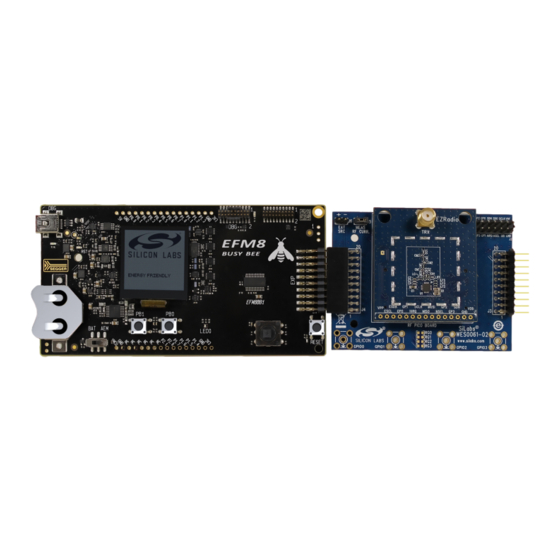
This document is intended to serve as a guide for application development with EZRa-
dio® Si4x55 ICs. It introduces the major parts of the hardware platform, such as the RF
Pico board, which contains the radio and the necessary RF components required to op-
erate the device according to a desired regulatory standard.
It introduces the energy friendly microcontroller 8-bit (EFM8) which is required to con-
trol the radio, evaluate the RF parameters, and develop custom application programs.
Besides the hardware, this document also describes the application programming inter-
face (API) that makes it possible for the EFM8 and RF Pico board to communicate with
each other. Using the software tools provided by Silicon Labs and following this pro-
gramming guide will make software development as easy as possible, as these items
will assist in configuring the radio effectively.
silabs.com | Smart. Connected. Energy-friendly.
KEY POINTS
• EFM8 along with an EZRadio is an ultra-
low cost two-chip wireless solution.
• The EZRadio is a sub-GHz wireless
communcation platform that can be a
receiver, transmitter, or tranciever.
• Configuration of the EZRadio can be done
with a simple GUI within a free tool
provided by Silicon Labs.
• Configuration of peripherals and pinouts on
the EFM8 is performed using an intuitive
GUI.
Rev. 0.1
Advertisement

Related Manuals for Silicon Laboratories EFM8


Summary of Contents for Silicon Laboratories EFM8
- Page 1 Besides the hardware, this document also describes the application programming inter- receiver, transmitter, or tranciever. face (API) that makes it possible for the EFM8 and RF Pico board to communicate with • Configuration of the EZRadio can be done each other. Using the software tools provided by Silicon Labs and following this pro-...
- Page 2 1. Hardware This section will introduce the hardware needed for this reference design and demo. Using an EFM8 along with an EZRadio is a two chip low cost wireless solution. This section will also discuss the connections between the radio, the MCU, and the expansion board used to connect the two.
-
Page 3: Antenna Connection
AN954: Programming Guide for EFM8 and EZRadio ® Hardware 1.3 RF Pico Card The RF pico board is a radio module that contains an EZRadio IC, a matching network, and an SMA connector on the top side. Other than the antenna connector, these components are covered by a metal shield for noise reduction. The digital signals of the radio (SCLK, SDI, SDO, NSEL, SCL, SDA, VDD and GND) can be accessed on test points at the edge of the board. - Page 4 1.4 Expansion Board The expansion (EXP) board is used to connect the EFM8 Starter Kit to the RF Pico board. It has two sets of headers on each side, one male, and one female. These are both mirrors of each other and can be used to transfer SPI, GPIOs, power, and ground. The RF Pico card sits on top of this EXP board via the RFP1/2 ports located in the middle of the EXP board.
- Page 5 AN954: Programming Guide for EFM8 and EZRadio ® Hardware RFP1 Connector RFP2 Connector MOSI MISO SCLK RF_NSEL RF_NIRQ RF_SDN RF_GPIO_0 RF_GPIO_1 RF_GPIO_2 RF_GPIO_3 Figure 1.5. RFP1 and RPF2 Connectors Table 1.1. EZRadio to EFM8 Connections Pin Name Pin Function BB1 STK Pin...
- Page 6 AN954: Programming Guide for EFM8 and EZRadio ® Hardware 1.6 Setting Up the Hardware 1. Connect an RF Pico Board to the expansion board via the RFP1/2 connectors. 2. Connect the antenna to the SMA connector on the RF Pico Board.
- Page 7 AN954: Programming Guide for EFM8 and EZRadio ® Software 2. Software The first step to getting started with the EFM8BB1 is download Simplicty Studio from the Silicon Labs website (http://www.silabs.com/ simplicity-studio). Follow the installation wizard for a complete install. More information on specific tools included in Simplicity Studio and their usage can be found at http://www.silabs.com/products/mcu/Pages/simplicity-studio.aspx.
- Page 8 AN954: Programming Guide for EFM8 and EZRadio ® Software After the desired configuration is selected, the program gives the option to generate a header file which will contain all of the options selected in the GUI. This file can then be used in a Simplicity Studio project to configure the radio and communicate with an MCU.
- Page 9 Note: WDS does not support EFM8 products. There are options to generate an entire project with MCU source code, however these projects and code will most likely not work on EFM8 MCUs. When working with EFM8 and EZRadio/PRO, WDS is only used to gener- ate the header file.
- Page 10 AN954: Programming Guide for EFM8 and EZRadio ® Software Figure 2.5. WDS Configuration The generated header file can be used in a new or existing project within Simplicity Studio, or used with any other IDE. silabs.com | Smart. Connected. Energy-friendly.
- Page 11 3.1 Range Test The Range test demo is an evaluation tool that allows the user to evaluate the combination of EFM8 and a sub-GHz radio. It has config- urable settings that the user can alter and measure to know how this combination will perform in a specific application.
- Page 12 AN954: Programming Guide for EFM8 and EZRadio ® Software Demos 1. Inset the RF Pico card 4. Connect the USB cable onto the EXP board from the STK to the host PC 2. Insert the EXP board onto 3. Flip the switch to AEM the STK via 20 pin header Figure 3.2.
- Page 13 AN954: Programming Guide for EFM8 and EZRadio ® Software Demos Figure 3.3. Example Project Tree — Range Test Some of the important files within the demo are described below. File Name: main.c Description: Contains all the logic for the demo, state controls, and API calls to the radio. Contains the screen outputs.
- Page 14 AN954: Programming Guide for EFM8 and EZRadio ® Software Demos Description: Contains hardware configurations of the 8-bit MCU including pin states, clocks, interrupts, SPI configuration, and more. File Name: radio.c/h Description: Contains the API functions, defines, and variables for the EZRadio. These functions add an abstraction layer for the user and allow higher level calls.
-
Page 15: Application Programming Interface
AN954: Programming Guide for EFM8 and EZRadio ® Application Programming Interface 4. Application Programming Interface The programming interface allows the user to do the following: • Send commands to the radio. • Read status information. • Set and read radio parameters. - Page 16 AN954: Programming Guide for EFM8 and EZRadio ® Application Programming Interface Command ID Name Description 0x19 IRCAL_MANUAL Image rejection calibration. TX_COMMANDS Switches to TX state and starts transmis- 0x31 START_TX sion of a packet. 0x37 TX_HOP Hop to a new frequency while in TX.
- Page 17 AN954: Programming Guide for EFM8 and EZRadio ® Application Programming Interface Return Value: None Note: Before this function should be called. si4455_reset Function Name: U8 si4455_configuration_init(const U8*pSetPropCmd) Description: This function is used to load all properties with a list of NULL terminated set property commands.
- Page 18 AN954: Programming Guide for EFM8 and EZRadio ® Application Programming Interface Return Value: None Function Name: void si4455_read_rx_fifo(U8 numBytes, U8* pRxData) Description: Reads the RX FIFO content from the radio. Input Parameter(s): numBytes: Data length to be read. pRxData: Pointer to the buffer location.
- Page 19 AN954: Programming Guide for EFM8 and EZRadio ® Application Programming Interface 4.3.3 NIRQ Interrupt Checking Method The radio asserts the CHIP_READY interrupt flag if a command is completed. The interrupt flag can be monitored by either the GET_CHIP_STATUS or the GET_INT_STATUS command. Apart from monitoring the interrupt flags, the radio may pull down the NIRQ pin if this feature is enabled.
- Page 20 AN954: Programming Guide for EFM8 and EZRadio ® Application Programming Interface Figure 4.4. Read Response From Radio If CTS is polled over the SPI bus, first the host MCU should pull the NSEL pin low. This action should be followed by sending out the 0x44 Read command ID and providing an additional eight clock pulses on the SCLK pin.
- Page 21 AN954: Programming Guide for EFM8 and EZRadio ® Application Programming Interface 4.5 Using Fast Response Registers There are several types of status information that can be read out from the radio faster. The FRR_CTL_x_MODE (where x can be A, B, C, or D) properties define what status information is assigned to a given fast response register (FRR).
- Page 22 AN954: Programming Guide for EFM8 and EZRadio ® Application Programming Interface Figure 4.8. Transmit FIFO Write If the host MCU needs to read the receive FIFO, it has to pull the NSEL pin low and send the 0x77 Receive FIFO Read command ID.
- Page 23 AN954: Programming Guide for EFM8 and EZRadio ® Radio Initialization 5. Radio Initialization 5.1 Radio Chip Wake Up First, the radio is in the off state. After the SDN pin is pulled low, the radio wakes up and performs a Power on Reset which takes a maximum of 5 ms until the chip is ready to receive commands on the SPI bus.
- Page 24 AN954: Programming Guide for EFM8 and EZRadio ® Radio Initialization Start SDN=1 Wait 1. Host MCU Host MCU pulls Initialize 10us down SDN pin of radio SDN=0 Optional checking 2. Radio Waiting GPIO1 went Power On 5ms for high? Reset...
- Page 25 AN954: Programming Guide for EFM8 and EZRadio ® Radio Initialization 5.2 State Transitions of the EZRadioPRO Devices Ready state is designed to give a fast transition time to TX or RX state with reasonable current consumption. The crystal oscillator re- mains enabled in this mode, reducing the time required to switch to TX or RX mode by eliminating the crystal start-up time.
- Page 26 AN954: Programming Guide for EFM8 and EZRadio ® Radio Initialization Table 5.1. Radio States State/Mode Response Time Shutdown 15 ms 15 ms Sleep 500 μs 500 μs SPI Active 340 μs 340 μs Ready 110 μs 120 μs TX Tune 60 μs...
- Page 27 AN954: Programming Guide for EFM8 and EZRadio ® Radio Initialization RX Chain calibration 400μs @ 10mA POR=1ms @ 1.25mA Reg. inrush = 5μs @ 2mA 5.5ms 10ms @ 2mA 5ms @ 1.8mA Standby = 50nA Shutdown = 30nA Power Up Configuration Figure 5.4.
- Page 28 AN954: Programming Guide for EFM8 and EZRadio ® Radio Initialization RX = 10.7mA RX Chain calibration 400μs @ 10mA POR=1ms @ 1.25mA Reg. inrush = 5μs @ 2mA 5.5ms 10ms @ 2mA 5ms @ 1.8mA Shutdown = 30nA Power Up Configuration Figure 5.6.
- Page 29 AN954: Programming Guide for EFM8 and EZRadio ® Radio Initialization 5.3 Radio Configuration File 5.3.1 Radio Initialization with RF Parameters The radio parameter configuration process can be accomplished by using the Wireless Development Studio (WDS). After the required parameters are given to the radio configuration application, WDS creates the configuration data based on these parameters. If the Launch IDE option is selected, WDS generates a header file that contains the configuration data.
- Page 30 AN954: Programming Guide for EFM8 and EZRadio ® Radio Initialization 5.3.2 Generated Radio Configuration File The configuration file is automatically generated by the "Radio Control Application" tool. It is interpreted as a C- header file called radio and it has four sections. The first two sections are intended for the users and allow them to see the exact values of the API _config.h...
- Page 31 AN954: Programming Guide for EFM8 and EZRadio ® Radio Initialization The Radio Setup Configuration in Definitions section is the list of initialization commands that are sent to the radio over the SPI inter- face. The structure of one element of the list is shown below. The comment lines describe how the C definition configures the dedicated API properties.
- Page 32 AN954: Programming Guide for EFM8 and EZRadio ® Radio Initialization #define CUSTOM_CHANNEL_NUMBER_RX 0 Root Directory Doxyfile application Cleanup.bat Drivers Radio Si446x/Si4455 Si446x_api_lib.c Si446x_api_lib.h Radio_hal.c Radio_hal.h Radio_comm.c Radio_comm.h Figure 5.10. Radio Driver File Location silabs.com | Smart. Connected. Energy-friendly. Rev. 0.1 | 31...
- Page 33 AN954: Programming Guide for EFM8 and EZRadio ® Patching the Radio 6. Patching the Radio A Radio patch is a piece of software provided by Silicon Labs to change the operation of the radio chip. The patch runs on the internal MCU of the radio chip and fixes bugs or adds/improves features of the firmware in the internal ROM.
-
Page 34: Additional Resources
AN954: Programming Guide for EFM8 and EZRadio ® Additional Resources 7. Additional Resources • AN796: Wireless Development Suite General Description — This document describes the WDS, its features and general usage: http://www.silabs.com/Support%20Documents/TechnicalDocs/an0822.pdf. • AN632: WDS User's Guide for EZRadioPRO®Devices — This document describes how to combine the EZRadio/Pro with WDS: https://www.silabs.com/Support%20Documents/TechnicalDocs/AN632.pdf. - Page 35 Trademark Information Silicon Laboratories Inc.® , Silicon Laboratories®, Silicon Labs®, SiLabs® and the Silicon Labs logo®, Bluegiga®, Bluegiga Logo®, Clockbuilder®, CMEMS®, DSPLL®, EFM®, EFM32®, EFR, Ember®, Energy Micro, Energy Micro logo and combinations thereof, "the world’s most energy friendly microcontrollers", Ember®, EZLink®, EZRadio®, EZRadioPRO®, Gecko®, ISOmodem®, Precision32®, ProSLIC®, Simplicity Studio®, SiPHY®, Telegesis, the Telegesis Logo®, USBXpress®...
Need help?
Do you have a question about the EFM8 and is the answer not in the manual?
Questions and answers