Table of Contents
Advertisement
Quick Links
C P2112 E
VALUATION
1. Kit Contents
The CP2112 Evaluation Kit contains the following items:
CP2112 Evaluation Board
CP2112 Product Information CD-ROM. CD contents include:
Example Windows and Mac Applications
Documentation:
CP2112 Data Sheet
CP2112 Evaluation Kit User's Guide
AN495: CP2112 Interface Specification
AN496: CP2112 HID USB-to-SMBus API Specification
USB Cable
2. Software Setup
The included CD-ROM contains the example applications for PC
the CD-ROM into a system's CD-ROM drive. If using a Windows PC, an installer will automatically launch, allowing
you to install the software or read documentation by clicking buttons on the Installation Panel. If the installer does
not automatically start when you insert the CD-ROM, run autorun.exe found in the root directory of the CD-ROM.
Refer to the ReleaseNotes CP211x CD.txt file on the CD-ROM for the latest information regarding versions and
known problems and restrictions. If a non-Windows PC is used, manually browse to the directory on the CD-ROM
that contains drivers for your OS. The instructions in this document assume that a Windows PC is being used.
3. CP2112 Hardware Interface
Connect the CP2112 evaluation board to a PC as shown in Figure 1.
1. Connect one end of the USB cable to a USB Port on the PC.
2. Connect the other end of the USB cable to the USB connector on the CP2112 evaluation board.
3. Connect the SDA, SCL, and Ground pins on the CP2112 to an SMBus device. External pull-up resistors
are not needed if the pull-up resistors on the CP2112 evaluation board are used.
P C
U SB Port
Rev. 0.2 9/10
K
U
I T
C P2112 Eval
B oard
U SB
C P2112
U SB
C able
Figure 1. Hardware Setup
Copyright © 2010 by Silicon Laboratories
C P 2 11 2 - E K
'
G
SER
S
UIDE
®
®
and Mac
and additional documentation. Insert
SD A
SC L
G N D
SM Bus
SD A
SC L
D evice
G N D
CP2112-EK
Advertisement
Table of Contents

Summary of Contents for Silicon Laboratories CP2112-EK
-
Page 1: Kit Contents
B oard SD A U SB SC L C P2112 G N D Figure 1. Hardware Setup Copyright © 2010 by Silicon Laboratories C P 2 11 2 - E K UIDE ® and additional documentation. Insert SM Bus SD A... - Page 2 SUSPEND LED on the CP2112 evaluation board will turn on. 2. Launch the HidSmbus Example application, which is found by clicking StartAll ProgramsSilicon LaboratoriesCP2112 Evaluation KitHidSmbus Example. 3. In this application, you can configure the SMBus settings and GPIO pins, customize the device descriptors, and read/write data over the SMBus interface.
- Page 3 Enter the Slave address in the “Write Request” box and data (in hex) in the “Data to Write” box. After this, click “Write Request” (shown in purple). Next, click Get Read/Write Transfer Status, and verify that the transfer was complete at the bottom of the application (shown in blue). Figure 3. Data Transfer Tab Rev. 0.2 CP2112-EK...
- Page 4 CP2112-EK 10. Figure 4 shows the Pin Configuration tab, which allows you to configure the GPIO and Special Functions (TX Toggle, RX Toggle, and Clock Output). GPIO pins toggle between Input/Ouput and Open-Drain/Push-Pull by clicking the corresponding GPIO boxes in the “GPIO Configuration”...
- Page 5 Customization Guide”. In order for these parameters to be sucessfully programmed, there must be a 4.7 µF capacitor connected between the VPP pin and ground. The CP2112-EK board has this capacitor. See "6. Schematic" on page 8 for more details on the evaulation board schematic.
-
Page 6: Target Board
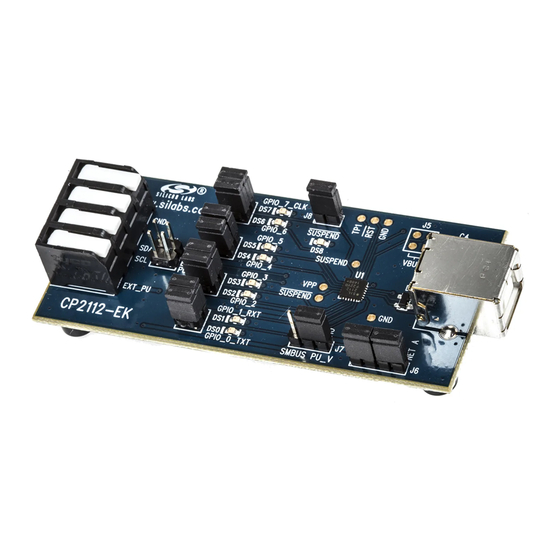
CP2112-EK 5. Target Board The CP2112 Evaluation Kit includes an evaluation board with a CP2112 device pre-installed for evaluation and preliminary software development. Numerous input/output (I/O) connections are provided to facilitate prototyping using the evaluation board. Refer to Figure 6 for the locations of the various I/O connectors. Refer to Figure 7, “CP2112 Evaluation Board Schematic”... - Page 7 The J8 header is used to connect the CP2112 SUSPEND pin (Pin 17) to the DS8 red LED. When the LED is on, the device has enumerated with the PC operating normally. When the LED is off, the device has not yet enumerated or is in the USB Suspend state. Pin # Description VBUS GND (Ground) Rev. 0.2 CP2112-EK...
- Page 8 CP2112-EK 6. Schematic Rev. 0.2...
-
Page 9: Document Change List
OCUMENT HANGE Revision 0.1 to Revision 0.2 Updated Figure 1. Updated "4. CP2112 Windows Application" on page Instructions and figures from updated PC application Updated Figure 7 on page 8. Rev. 0.2 CP2112-EK... -
Page 10: Contact Information
Silicon Laboratories products are not designed, intended, or authorized for use in applications intended to support or sustain life, or for any other application in which the failure of the Silicon Laboratories product could create a situation where per- sonal injury or death may occur.


Need help?
Do you have a question about the CP2112-EK and is the answer not in the manual?
Questions and answers