Table of Contents
Advertisement
Quick Links
C P2112 E
VALUATION
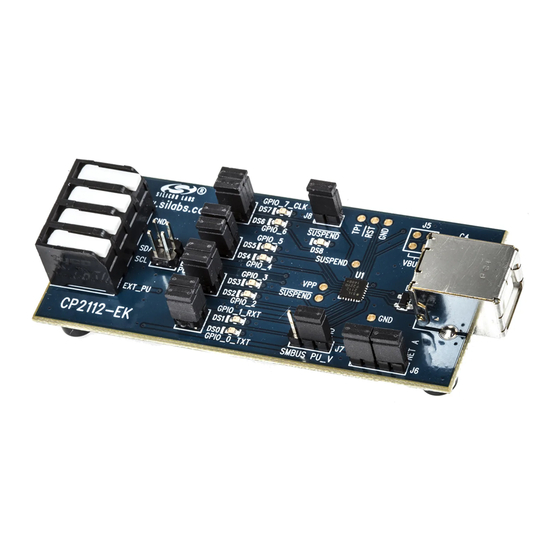
1. Kit Contents
The CP2112 Evaluation Kit contains the following items:
CP2112 Evaluation Board
USB Cable
DVD
Quick Start Guide
2. Relevant Documentation
Application notes can be found on the Interface Application Notes page for all fixed-function devices:
www.silabs.com/interface-appnotes.
AN721: CP210x/CP211x Device Customization Guide — Customize the VID, PID, serial number, and
other parameters stored in the CP2112 one-time programmable ROM.
AN496: CP2112 HID-to-SMBus API Specification — Provides function descriptions and examples for all
of the PC software functions that control the CP2112.
AN495: CP2112 Interface Specification — Describes the HID report format for CP2112 devices.
3. Software Setup
The Software Development Kit (SDK) for the
installer can also be downloaded from the
Device Customization Utility
Documentation — data sheet, application notes, user's guide, quick start guide, etc.
HidSmbusExample — Example software utilizing the CP2112 API interface described in AN496.
Library — repackaged HID DLL and CP2112 API DLL
The Windows installer should launch automatically after inserting the
appropriate directory on the
system. The CP2112 is an HID device, so a driver does not need to be installed on most operating systems.
Rev. 0.3 7/13
K
U
I T
CP2112
www.silabs.com/cp2112ek
to install the software package. Follow the instructions to install the SDK to the
DVD
Copyright © 2013 by Silicon Laboratories
C P 2 11 2 - E K
'
G
SER
S
UIDE
kit is included on the kit DVD. The latest version of this
website. This package includes:
. For Mac and Linux, browse to the
DVD
CP2112-EK
Advertisement
Table of Contents

Related Manuals for Silicon Laboratories CP2112


Summary of Contents for Silicon Laboratories CP2112
-
Page 1: Kit Contents
Follow the instructions to install the SDK to the system. The CP2112 is an HID device, so a driver does not need to be installed on most operating systems. Rev. 0.3 7/13 Copyright ©... - Page 2 2. Connect one end of the USB cable to a USB Port on the PC. 3. Connect the other end of the USB cable to the USB connector on the CP2112 evaluation board. 4. Connect the SDA, SCL, and Ground pins on the CP2112 to an SMBus device. External pull-up resistors are not needed if the pull-up resistors on the CP2112 evaluation board are used.
- Page 3 HID report structure for the CP2112, and AN496, “CP2112 HID-to-SMBus API Specification” describes the API software functions that can be used to read or write data and control the CP2112 from the PC. The software application described in “6. CP2112 Windows Application” provides an example of how to use these functions.
- Page 4 The HID SMBus Example application uses the Windows CP2112 HID-to-SMBus DLL to transmit and receive data with the CP2112. The application also has access to the CP2112’s GPIO pins. Figure 3 shows a screenshot of the Windows Application. The following steps describe how to start the application and use some of its features.
- Page 5 Next, click Force Read Response and then Get Read Response until the application reads back the total number of bytes. The bytes will be shown in the Received Data field. The status of the CP2112 will be shown at the bottom of the application.
- Page 6 Click Force Read Response and then Get Read Response until the application reads back the total number of bytes. The bytes will be shown in the Received Data field. The status bar of the application displays the current status of the CP2112. Figure 5. Performing an Addressed Read using the Example Application...
- Page 7 CP2112-EK 8. To write data over the SMBus interface: a. Click the Data Transfer tab. Enter the Slave address and data (in hex) in the Write Request box. Click the Write Request button. Click Get Read/Write Transfer Status and verify that the transfer completed using the status bar at the bottom of the application.
- Page 8 The Latch Values section enables writing or reading the GPIO latches. Clicking the box next the GPIO pins listed will scroll through 1, 0, and X for a don’t care. Click the Write Latch button to change the state of the GPIO latch. Figure 7. Configuring the CP2112 Pins using the Example Application Rev. 0.3...
- Page 9 CP2112 software package. In order for these parameters to be sucessfully programmed, a 4.7 µF capacitor must be connected between the VPP pin and ground. This capacitor is populated by default on the CP2112 Evaluation Kit board has this capacitor. See "8. Schematic" on page 12 for more information.
- Page 10 7.1. LED Headers (J1, J2, J3, J4) Connectors J1, J2, J3, and J4 are provided to allow access to the GPIO pins on the CP2112. Place shorting blocks on J1, J2, J3, and J4 to connect the GPIO pins to the eight green LEDs, DS0–DS7. These LEDs can be used to indicate active communications through the CP2112.
- Page 11 7.6. SUSPEND LED Connector (J8) The J8 header is used to connect the CP2112 SUSPEND pin (Pin 17) to the DS8 red LED. When the LED is on, the device has enumerated with the PC operating normally. When the LED is off, the device has not yet enumerated or is in the USB Suspend state.
- Page 12 CP2112-EK 8. Schematic Rev. 0.3...
- Page 13 Added “2. Relevant Documentation” and “5. CP2112 Software Interface”. Updated “3. Software Setup” to point to the drivers on the website. Updated Figure 1. Updated the instructions and figures in “6. CP2112 Windows Application”. Rev. 0.3...
- Page 14 Silicon Laboratories products are not designed, intended, or authorized for use in applications intended to support or sustain life, or for any other application in which the failure of the Silicon Laboratories product could create a situation where per- sonal injury or death may occur.
Need help?
Do you have a question about the CP2112 and is the answer not in the manual?
Questions and answers