CKD ECG Series Instruction Manual
Controller for electric actuators io-link specifications
Hide thumbs
Also See for ECG Series:
- Instruction manual (262 pages) ,
- Instruction manual (59 pages) ,
- Instruction manual (110 pages)
Table of Contents
Advertisement
Quick Links
Controller for Electric Actuators
ECG Series
IO-Link Specifications
INSTRUCTION MANUAL
SM-A40831-A
Instruction Manual
• Be sure to read this instruction manual before using the product.
• Pay especially close attention to the safety-related information contained within.
• Keep this instruction manual in a safe place so that it is readily available when needed.
CKD Corporation
Advertisement
Table of Contents

Related Manuals for CKD ECG Series


Summary of Contents for CKD ECG Series
- Page 1 Controller for Electric Actuators ECG Series IO-Link Specifications INSTRUCTION MANUAL SM-A40831-A Instruction Manual • Be sure to read this instruction manual before using the product. • Pay especially close attention to the safety-related information contained within. • Keep this instruction manual in a safe place so that it is readily available when needed.
-
Page 2: Preface
PREFACE PREFACE Thank you for purchasing CKD controller for electric actuators “ECG Series IO-Link Specifications.” In order for this product to be used to its fullest potential, this instruction manual describes basic topics such as how to mount and use it. Read this manual thoroughly prior to use. -
Page 3: Safety Information
Ensure to observe organization’s standards, laws and regulations etc. for safety related to design and management of the equipment. It is important to select, use, handle and maintain CKD products appropriately to ensure their safe usage. Be sure to observe the warnings and precautions listed in this instruction manual to ensure equipment safety. -
Page 4: Product Precautions
SM-A40831-A SAFETY INFORMATION Product precautions DANGER Do not use this product for the following applications. • Medical devices involved in maintaining or managing human life or health • Mechanisms or machines meant to transfer or transport people • Important security parts in machines WARNING The product must be handled by the person who has sufficient knowledge and experience. -
Page 5: Table Of Contents
SM-A40831-A CONTENTS CONTENTS PREFACE ........................... i SAFETY INFORMATION ....................ii Product precautions ....................... iii Disposal precautions ..................... iii CONTENTS ........................iv PRODUCT OVERVIEW ..................... 1 System Overview ....................1 1.1.1 System structure..................... 1 Instruction Manuals Related to This Product ............4 Names of Parts .................... -
Page 6: Product Overview
SM-A40831-A 1. PRODUCT OVERVIEW 1. PRODUCT OVERVIEW 1.1 System Overview Windows is a registered trademark of Microsoft Corporation in the United States, Japan, and • other countries. Other company and product names in this document are company’s trademarks or • registered trademarks. - Page 7 Noise filter Provided for free PC setting software S-Tools When using this product as a European standard-compliant product, refer to “6 Product Compliance” in the instruction manual for the ECG series electric actuator controller (SM-A27751) and follow the instructions. 2021-01-08...
- Page 8 SM-A40831-A 1. PRODUCT OVERVIEW ◼ ECG-B Series 2021-01-08...
-
Page 9: Instruction Manuals Related To This Product
1.2 Instruction Manuals Related to This Product This manual provides explanation of the IO-Link specifications of the ECG series controller. For mounting and setting parameter and point data, refer to the instruction manual for the ECG series electric actuator controller (SM-A27751). -
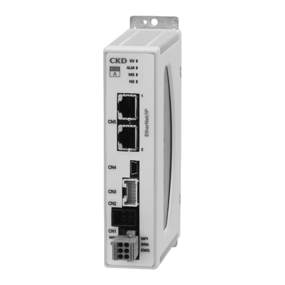
Page 10: Names Of Parts
SM-A40831-A 1. PRODUCT OVERVIEW 1.3 Names of Parts 1.3.1 LED Name Color Explanation Lights up when receiving normal data from a PLC. Green Turns off when time is over. Lights up according to the status of the set operation mode (IO-Link) upon startup. It then turns off, but blinks if an error occurs. -
Page 11: Specifications
Note 1: When setting the data with the IO-Link master (PLC), if the data table cannot be set with the data length shown here, the data table is generally mapped to be larger than this data length. Note 2: Indicates CKD Corporation. Note 3: Indicates this product. -
Page 12: Dimensions
SM-A40831-A 1. PRODUCT OVERVIEW 1.5 Dimensions ◼ Normal mounting ◼ DIN rail mounting Grounding terminal (M3 5 pan head screw) 2021-01-08... -
Page 13: Installation
SM-A40831-A 2. INSTALLATION 2. INSTALLATION DANGER Do not use in locations with ignitable, flammable, or explosive substances or other such dangerous substances. There may be risk of ignition, combustion, or explosion. Make sure that the product does not come in contact with water drops or oil drops. Fire or damage may result. -
Page 14: Wiring Method
SM-A40831-A 2. INSTALLATION 2.1 Wiring method WARNING Perform the wiring with the power supply turned OFF. Touching the electrical wiring connections (bare charger) may cause electric shock. Do not touch the charger with bare hands. Doing so may cause electric shock. Read and fully understand this instruction manual before performing the electrical wiring. -
Page 15: Connection And Wiring To Cn5 (Interface Connector)
Core wire stranded wire Strip length 10 mm from the tip of the lead wire 2.1.2 Other connections and wiring For other connection methods, refer to the instruction manual (SM-A27751) of the controller for the electric actuator ECG series. 2021-01-08... -
Page 16: Usage
When using the ECG-B Series, ensure to set the actuator information using S-Tools. Refer to • the S-Tools instruction manual (SM-A11147) for setting the information. To use S-Tools with the settings of the ECG Series (IO-Link specifications), the S-Tools • version must be as follows: ECG Series (IO-Link specifications): Version 1.04.00.00 or later... - Page 17 The product operates in 7 operation modes: PIO mode (5 Types), simple direct value mode and full direct value mode, and each mode uses a different IODD file. Select one according to the operation mode. 【When using ECG-A】 Mode File name Standard 64-point mode CKD-ECG-A-PIOMODE-B064-yyyymmdd-IODDvvv.xml Simple 7-point mode CKD-ECG-A-PIOMODE-S007-yyyymmdd-IODDvvv.xml Solenoid valve mode, double 2- CKD-ECG-A-PIOMODE-VW2P-yyyymmdd-IODDvvv.xml position type Solenoid valve mode, double 3- CKD-ECG-A-PIOMODE-VW3P-yyyymmdd-IODDvvv.xml...
-
Page 18: Io-Link Device Settings
SM-A40831-A 3. USAGE 3.2 IO-Link device settings In order to connect this product to the relevant port setting of the IO-Link master as an IO-Link device, it is necessary to set the device ID, process data, process data length, etc. using the PLC development tool. -
Page 19: Communication Format
SM-A40831-A 3. USAGE 3.3 Communication format 3.3.1 Data communication Type of data communication Description Data are periodically transmitted between the IO-Link master and the ECG based on the data frame with the size specified by the Cyclic communication device. Refers to PD (Process Data) communication. Upper devices such as PLC access any data in the ECG via the IO-Link master when necessary. - Page 20 SM-A40831-A 3. USAGE ◼ Write data and read data The point data and parameters are set, and the alarm history is read. Data is written and read by transmitting and receiving service data. <To read data> Specify Index and Subindex of the data to be read, and execute reading. <To write data>...
-
Page 21: Operation Mode
SM-A40831-A 3. USAGE 3.3.3 Operation mode There are three operation modes (IO-Link) as follows. The PIO mode can be changed among the 5 types according to the setting of operation mode (PIO). Name Abbreviation Operation mode (IO-Link) PIO mode Simple direct value mode Full direct value mode ◼... -
Page 22: Process Data
SM-A40831-A 3. USAGE 3.3.4 Process data The controller is operated from the PLC by operating the items described later with process data. In addition, the present position can be monitored. Process data are cyclically exchanged between the IO-Link master and the IO-Link device. The data length and structure are set using the connection settings of the PLC development tool and the relays and data memory are assigned. - Page 23 Note 4: The alarm 0 to 15 indicates the first digit of the alarm code as a hexadecimal number. For more detail, refer to “Signal name list” of “2.3.3. I/O cable wiring” in the instruction manual for the ECG series electric actuator controller (SM-A27751). For alarm codes, refer to “5.1 Alarm Indications and Countermeasures”...
- Page 24 SM-A40831-A 3. USAGE <Simple direct value mode (operation mode (IO-Link): 1)> Index 0x0028 Value Byte order Item Subindex Format (decimal) Note 1 Operation preparation 0: Incomplete, 1: Complete Boolean complete Warning Note 2 0: Triggered, 1: Not triggered Boolean Alarm Note 2 0: Triggered, 1: Not triggered Boolean...
- Page 25 SM-A40831-A 3. USAGE Index 0x0028 Value Byte order Item Subindex Format (decimal) Note 1 PD(in)#3 (4th byte) PD(in)#4 (5th byte) Present position (0.01 mm) (0.01 deg) -999999 to 999999 Integer32 Note 2 PD(in)#5 (6th byte) PD(in)#6 (7th byte) PD(in)#7 (8th byte) Depends on PD(out) data selection 2: Speed [mm/s] [deg/s] Monitor value...
- Page 26 SM-A40831-A 3. USAGE <Full direct value mode (operation mode (IO-Link): 2)> Index Value 0x0029 Byte order Item Format (decimal) Subindex Note 1 Operation preparation 0: Incomplete, 1: Complete Boolean complete Warning Note 2 0: Triggered, 1: Not triggered Boolean Alarm Note 2 0: Triggered, 1: Not triggered Boolean...
- Page 27 SM-A40831-A 3. USAGE Index Value 0x0029 Byte order Item Format (decimal) Subindex Note 1 PD(in)#3 (4th byte) PD(in)#4 (5th byte) Position (0.01 mm) (0.01 deg) -999999 to 999999 Integer32 Note 2 PD(in)#5 (6th byte) PD(in)#6 (7th byte) PD(in)#7 (8th byte) Speed (mm/s) (deg/s) 0 to 9999 UInteger16...
- Page 28 SM-A40831-A 3. USAGE ◼ Process data output/PD(out) Set data to write from the PLC to the controller. <PIO mode (operation mode (IO-Link): 0) Example: 64-point mode (operation mode (PIO): 0)> Index 0x0029 Item Value Byte order Subindex Format Note 1 (decimal) Note 2 Stop...
- Page 29 SM-A40831-A 3. USAGE <Simple direct value mode (operation mode (IO-Link): 1)> Index Item Value 0x0029 Byte order Format Note 1 (decimal) Subindex Note 2 Pause 0: Pause start, 1: Cancel Boolean Stop 0: Stop, 1: Cancel Boolean Alarm reset 0: -, 1: Reset Boolean Servo ON 0: Servo ON release 1: Servo ON...
- Page 30 SM-A40831-A 3. USAGE Index Item Value 0x0029 Byte order Format Note 1 (decimal) Subindex Note 2 PD(out)#3 (4th byte) PD(out)#4 (5th byte) Position -999999 to 999999 Integer32 (0.01 mm) (0.01 deg) PD(out)#5 (6th byte) PD(out)#6 (7th byte) Note 1: The value of each item stored in the PLC will not change unless a new value is written. (Note that it may change depending on PLC settings.) The PLC power-on value is stored as 0 or the last value written at the previous start-up.
- Page 31 SM-A40831-A 3. USAGE <Full direct value mode (operation mode (IO-Link): 2)> Index Item Value 0x0029 Byte order Format Note 1 (decimal) Subindex Note 2 Pause 0: Pause start, 1: Cancel Boolean Stop 0: Stop, 1: Cancel Boolean Alarm reset 0: -, 1: Reset Boolean Servo ON 0: Servo ON release 1: Servo ON...
- Page 32 SM-A40831-A 3. USAGE Index Item Value 0x0029 Byte order Format Note 1 (decimal) Subindex Note 2 PD(out)#11 Acceleration 0 to 255 (Use the common parameter UInteger8 (12th byte) (0.01 G) values if setting is 0) Note 6 PD(out)#12 Deceleration 0 to 255 (Use the common parameter UInteger8 (13th byte) (0.01 G)
- Page 33 SM-A40831-A 3. USAGE When starting, first confirm the status of communication with the PLC and IO-Link master for • the alarm signal, warning signal, and other signals, and then reference the status. Similarly, if communication is not established, it will not be sent to the controller even if each bit is ON (“1”).
-
Page 34: Pio Mode Process Data Details
SM-A40831-A 3. USAGE 3.3.5 PIO mode process data details ◼ 64-point (B064) (operation mode (PIO): 0) PD(in): Controller → PLC Value Index 0x0028 Byte order Descriptions Format (decimal) Subindex Operation preparation complete 0: Incomplete, 1: Complete Boolean Alarm 0: Triggered, 1: Not triggered Boolean Servo ON state 0: OFF state, 1: ON state... - Page 35 SM-A40831-A 3. USAGE PD(out): PLC → controller Value Index 0x0029 Byte order Descriptions Format (decimal) Subindex Stop 0: Stop, 1: Cancel Boolean Alarm reset 0: -, 1: Reset Boolean Servo ON 0: Servo ON release, 1: Servo ON Boolean PD(out)#0 Home position return start 0: -, 1: Home position return starts Boolean...
- Page 36 SM-A40831-A 3. USAGE ◼ Simple 7-point mode (S007) (operation mode (PIO): 1) PD(in): Controller → PLC Value Index 0x0028 Byte order Descriptions Format (decimal) Subindex Operation preparation complete 0: Incomplete, 1: Complete Boolean Alarm 0: Triggered, 1: Not triggered Boolean Servo ON state 0: OFF state, 1: ON state Boolean...
- Page 37 SM-A40831-A 3. USAGE PD(out): PLC → controller Value Index 0x0028 Byte order Descriptions Format (decimal) Subindex Stop 0: Stop, 1: Cancel Boolean Alarm reset 0: -, 1: Reset Boolean Servo ON 0: Servo ON release, 1: Servo ON Boolean PD(out)#0 Home position return start 0: -, 1: Home position return starts Boolean...
- Page 38 SM-A40831-A 3. USAGE ◼ Solenoid valve mode, double 2-position type (VW2P) (operation mode (PIO): 2) PD(in): Controller → PLC Value Index 0x0028 Byte order Descriptions Format (decimal) Subindex Operation preparation complete 0: Incomplete, 1: Complete Boolean Alarm 0: Triggered, 1: Not triggered Boolean Servo ON state 0: OFF state, 1: ON state...
- Page 39 SM-A40831-A 3. USAGE PD(out): PLC → controller Value Index 0x0028 Byte order Descriptions Format (decimal) Subindex Alarm reset 0: -, 1: Reset Boolean Servo ON 0: Servo ON release, 1: Servo ON Boolean PD(out)#0 Home position return start 0: -, 1: Home position return starts Boolean PD(out)#1 Solenoid valve travel command 2...
- Page 40 SM-A40831-A 3. USAGE ◼ Solenoid valve mode, double 3-position type (VW3P) (operation mode (PIO): 3) PD(in): Controller → PLC Value Index 0x0028 Byte order Descriptions Format (decimal) Subindex Operation preparation complete 0: Incomplete, 1: Complete Boolean Alarm 0: Triggered, 1: Not triggered Boolean Servo ON state 0: OFF state, 1: ON state...
- Page 41 SM-A40831-A 3. USAGE PD(out): PLC → controller Value Index 0x0028 Byte order Descriptions Format (decimal) Subindex Alarm reset 0: -, 1: Reset Boolean Servo ON 0: Servo ON release, 1: Servo ON Boolean PD(out)#0 Home position return start 0: -, 1: Home position return starts Boolean PD(out)#1 Solenoid valve travel command 2...
- Page 42 SM-A40831-A 3. USAGE ◼ Solenoid valve mode, single type (VSGL) (operation mode (PIO): 4) PD(in): Controller → PLC Index Value Byte order Descriptions 0x0028 Format (decimal) Subindex Operation preparation complete 0: Incomplete, 1: Complete Boolean Alarm 0: Triggered, 1: Not triggered Boolean Servo ON state 0: OFF state, 1: ON state...
- Page 43 SM-A40831-A 3. USAGE PD(out): PLC → controller Index Value Byte order Descriptions 0x0028 Format (decimal) Subindex Alarm reset 0: -, 1: Reset Boolean Servo ON 0: Servo ON release, 1: Servo ON Boolean PD(out)#0 Home position return start 0: -, 1: Home position return starts Boolean PD(out)#1 Solenoid valve travel command...
-
Page 44: Service Data
SM-A40831-A 3. USAGE 3.3.6 Service Data With service data (on-request data, message communication), the point data and parameters are set, and the alarm history is read. The controller is operated from the PLC by transmitting and receiving service data. Also, process data can be read as service data. Process data input Index: 0x0028 Process data output... - Page 45 SM-A40831-A 3. USAGE ◼ Access example 3: Transmitting a message to the controller from the IO-Link master The following object format provides only the information necessary for explaining the data writing and reading examples described later. Since the format differs depending on the object used, refer to the manual for the IO-Link master for details on the object.
- Page 46 SM-A40831-A 3. USAGE If the entire data composed of multiple elements (data with multiple Subindex data) is • accessed with Subindex = 0, some items (such as the point data “Position specification method”) will have bit configuration. Refer to “3.3 Communication format” for details. •...
- Page 47 OFF/ON. (1) Identification Index Value Data Item Access Format (hexadecimal) index (decimal) length 0x0010 Vendor Name CKD Corporation 64 byte String 0x0011 Vender Text https://www.ckd.co.jp/ 64 byte String ECG-A:ECG-ANNN30-LK 0x0012 Product Name 64 byte String ECG-B:ECG-BNNN30-LK...
- Page 48 SM-A40831-A 3. USAGE <Product ID and DeviceID3> 【ECG-A】 Operation mode Product ID Device ID 3 Standard 64-point mode ECG-ANNN30-LK_PIO_MODE(B064) 0x03 Simple 7-point mode ECG-ANNN30-LK _PIO_MODE(S007) 0x04 Solenoid mode ECG-ANNN30-LK _PIO_MODE(VW2P) 0x05 Double 2-position type PIO mode Solenoid mode ECG-ANNN30-LK _PIO_MODE(VW2P) 0x06 Double 3-position type Solenoid mode...
- Page 49 SM-A40831-A 3. USAGE (2) Parameter and commands Common specifications Index Value Data (hexadecimal Item Access Format Index (decimal) length Note 2 System 0x0002 Refer to the table “System Command.” 1byte UInteger8 Command Device 0x0000: No lock 0x000C Access 0x0001: Parameter lock 2byte Record ●...
- Page 50 SM-A40831-A 3. USAGE Individual specifications 1 (Vendor) Index (Hexade Value Data Item Access Format cimal index (Decimal number) length Note 1 number) 0: PIO mode Operation mode (IO-Link) 0x0041 1: Simple direct value mode 1byte UInteger8 Note 2 2: Full direct value mode Data Storage mode 0x0042 1: Forced upload...
- Page 51 SM-A40831-A 3. USAGE Individual specifications 2 Index Value Data (Hexadeci Item Access Format Note Index (decimal) length mal) Point data 0x1000 0 to 63 2 byte UInteger16 number specification Point data Note 2 30 byte Record ● Position Negative stroke length to positive stroke 4 byte Integer32 (0.01 mm) (0.01 deg)
- Page 52 SM-A40831-A 3. USAGE Individual specifications 3 Index Value Data (Hexade Inde Item Access Format Note (decimal) length cimal) Soft limit (+) Note 2: 0x0302 -999999 to 999999 4 byte Integer32 ● (0.01 mm) (0.01 deg) Soft limit (-) Note 2: 0x0304 -999999 to 999999 4 byte...
- Page 53 SM-A40831-A 3. USAGE Individual specifications 4 Index Value Acces Data (Hexade Item Format Index (decimal) length cimal) Common positioning width 0x0319 1 to 999 2 byte UInteger16 (0.01 mm) (0.01 deg) 0x031A Common speed (mm/s) (deg/s) 1 to 9999 2 byte UInteger16 Common acceleration 0x031B...
- Page 54 SM-A40831-A 3. USAGE Individual specifications 6 Index Value Data (Hexade Item Access Format Index (decimal) length cimal) Controller model number 0x0400 40 byte String Controller serial number 0x0401 16 byte String Actuator model number 0x0402 40 byte String Actuator serial number 0x0403 16 byte String...
- Page 55 SM-A40831-A 3. USAGE ◼ Return error When reading/writing data, following error codes are set as FB output parameters for the set input parameters. If CoE object is used, the error codes are set to Subindex = 0x07 (Errorcode) of the corresponding Index (such as 0x4000).
-
Page 56: Operation Time Chart
SM-A40831-A 3. USAGE 3.4 Operation time chart 3.4.1 Servo ON WARNING Keep safety in mind. When turning servo OFF during operation, operation may continue with the inertia of the workpiece. CAUTION When turning the servo ON, check that the actuator operates safely. The actuator could start operating once the servo is turned ON, which could cause injury or damage the workpiece. -
Page 57: From Power-On To Home Position Return
SM-A40831-A 3. USAGE 3.4.2 From power-on to home position return The diagram below shows the timing of home position return completion from the beginning of the return after the power is turned on. Horizontal axis: Time Control power Power supply Motor power Green Controller display... -
Page 58: Home Position Return Operation
SM-A40831-A 3. USAGE 3.4.3 Home position return operation When a home position return operation is executed, a home position return operation is performed. The position at which home position return operation completes becomes the home position (0 mm). Position after Position after 原点復帰後... -
Page 59: Positioning Operation
SM-A40831-A 3. USAGE 3.4.4 Positioning operation ◼ Point operation <Designating a stop during travel> Horizontal axis: Time Point travel start Stop (Negative logic) PD(out) The traveling Point number point number is designated selection in binary code. Displacement 変位 Point 7 Displacement Point 3 Point 1... - Page 60 SM-A40831-A 3. USAGE <Designating a pause during travel> Horizontal axis: Time Point travel start Pause (Negative logic) PD(out) The traveling Point number point number is designated selection in binary code. Displacement Displacement Point 7 Displacement Point 3 Point 1 Point travel Note 2 complete Traveling...
- Page 61 SM-A40831-A 3. USAGE ◼ Direct value operation <Simple direct value mode and Half simple direct value mode> Check that the point data for the point number to be specified by PD (out) is set. Set the position and point number in PD (out). Set Direct value travel selection to ON.
- Page 62 SM-A40831-A 3. USAGE <Full direct value mode and Half direct value> After setting point data such as position and speed in PD (out), turn ON the point travel start bit. Horizontal axis: Time Point travel start Direct value PD (out) travel selection Point data...
- Page 63 SM-A40831-A 3. USAGE <Direct value travel selection and direct travel status> Turn ON the direct value travel selection. When the direct value travel starts, the direct value travel status is turned ON, and it stays ON until the next point travel starts. (It remains ON even when the servo OFF.) Horizontal axis: Time Point travel start PD(out)
-
Page 64: Errors And Obtaining Error Codes
SM-A40831-A 3. USAGE 3.4.5 Errors and obtaining error codes Horizontal axis: Time 横軸:時間 アラーム アラーム Alarm (in) (Negative logic) (b接点) (b接点) 取得 Obtained エラーコード Error code 注1 Note 1 エラ ー Error エラ ー Error 発生 解除 release occurs Note 1: Obtain Alarm (Index = 0x70A) or Alarm details (Index = 480) with service data. 2021-01-08... -
Page 65: Data Storage (Ds) Function
SM-A40831-A 3. USAGE 3.5 Data Storage (DS) Function Data Storage function is a function that backs up the IO-Link device setting parameter data for each port of the IO-Link master. With this function, the backup data can be restored as necessary, such as when the IO-Link device is replaced due to a failure. -
Page 66: Download/Upload
SM-A40831-A 3. USAGE 3.5.3 Download/Upload ◼ Download If the backup data stored in the IO-Link master does not match the parameter data set in the connected IO-Link device at startup, the IO-Link master downloads the stored backup data. Therefore, if the controller is replaced with a backup controller for reasons such as a controller failure, the minimum setting data required for operation can be written to the new controller. - Page 67 SM-A40831-A 3. USAGE ◼ DS Upload/Download target items Item Size Device Access Locks 2 byte Application Specific Tag 32 byte Output selection 1 1 byte Output selection 2 1 byte Home position return speed 2 byte Automatic home position return 2 byte Fixed current at stop 2 byte...
-
Page 68: Error Events
SM-A40831-A 3. USAGE 3.6 Error events When an error occurs with the controller, an error generation event is sent to the IO-Link Master. When the error is released, an error release event is sent to the IO-Link Master. Event code Description **: Sets the error code type. -
Page 69: Warranty Provisions
If the product specified herein fails for reasons attributable to CKD within the warranty period specified below, CKD will promptly provide a replacement for the faulty product or a part thereof or repair the faulty product at one of CKD's facilities free of charge.
Need help?
Do you have a question about the ECG Series and is the answer not in the manual?
Questions and answers