CKD ECG Series Instruction Manual
Controller for electric actuators
Hide thumbs
Also See for ECG Series:
- Instruction manual (262 pages) ,
- Instruction manual (69 pages) ,
- Instruction manual (68 pages)
Table of Contents
Advertisement
Quick Links
Controller for Electric Actuators
ECG Series
INSTRUCTION MANUAL
INSTRUCTION MANUAL
SM-A27751-A/3
MSV-484083
• Be sure to read this instruction manual before using the product.
• Pay especially close attention to the safety-related information contained within.
• Keep this instruction manual in a safe place so that it is readily available when needed.
CKD Corporation
Advertisement
Table of Contents

Related Manuals for CKD ECG Series


Summary of Contents for CKD ECG Series
- Page 1 Controller for Electric Actuators ECG Series INSTRUCTION MANUAL INSTRUCTION MANUAL SM-A27751-A/3 MSV-484083 • Be sure to read this instruction manual before using the product. • Pay especially close attention to the safety-related information contained within. • Keep this instruction manual in a safe place so that it is readily available when needed.
-
Page 2: Preface
PREFACE PREFACE Thank you for purchasing this CKD “ECG” controller for electric actuators. This Instruction Manual contains basic matters such as installation and usage instructions in order to ensure optimal performance of the product. Please read this Instruction Manual thoroughly and use the product properly. -
Page 3: Safety Information
Therefore, confirm that the safety of the equipment's mechanisms and the system that runs the electrical controls can be ensured. It is important to select, use, handle and maintain CKD products appropriately to ensure their safe usage. Be sure to observe the warnings and precautions listed in this instruction manual to ensure equipment safety. -
Page 4: Product Precautions
SM-A27751-A/3 SAFETY INFORMATION Product precautions DANGER Do not use this product for the following applications. • Medical devices involved in maintaining or managing human life or health • Mechanisms or machines meant to transfer or transport people • Important security parts in machines WARNING The product must be handled by the person who has sufficient knowledge and experience. -
Page 5: Table Of Contents
SM-A27751-A/3 CONTENTS CONTENTS PREFACE ........................... i SAFETY INFORMATION ....................ii Product precautions ....................... iii Disposal precautions ..................... iii CONTENTS ........................iv PRODUCT OVERVIEW ..................... 1 System Overview ....................1 System Structure and Workflow (ECG-A Series) ......... 1 System Structure and Workflow (ECG-B Series)......... 3 Instruction Manuals Related to This Product ............ -
Page 6: Contents
SM-A27751-A/3 CONTENTS OPERATION ..................... 62 Emergency stop and release ..............62 Force brake release ................... 63 Servo ON/OFF .................... 64 From power-on to home position return ............. 65 Home position return operation ..............66 Positioning operation .................. 76 Other output signals ................... 87 Pressing operation .................. -
Page 7: Product Overview
SM-A27751-A/3 1. PRODUCT OVERVIEW 1. PRODUCT OVERVIEW 1.1 System Overview Check “1.1.1 System Structure and Workflow (ECG-A Series)” if you have purchased the ECG-A Series and “1.1.2 System Structure and Workflow (ECG-B Series)” if you have purchased the ECG-B Series. System Structure and Workflow (ECG-A Series) ◼... - Page 8 SM-A27751-A/3 1. PRODUCT OVERVIEW System components that can be purchased from CKD are listed below. Component Product name/Model no. This product Controller ECG-A Series Power supply connector DFMC 1,5/ 3-STF-3,5 (PHOENIX CONTACT) Accessories I/O cable EA-CBLNP2- * Actuator EBS-G/EBR-G Series...
-
Page 9: System Structure And Workflow (Ecg-B Series)
SM-A27751-A/3 1. PRODUCT OVERVIEW System Structure and Workflow (ECG-B Series) ◼ System structure 2021-11-18... - Page 10 SM-A27751-A/3 1. PRODUCT OVERVIEW System components that can be purchased from CKD are listed below. Component Product name/Model no. This product Controller ECG-B Series Power supply connector DFMC 1,5/ 3-STF-3,5 (PHOENIX CONTACT) Accessories I/O cable EA-CBLNP2-* Actuator FLSH-G/FLCR-G/FGRC-G Series Motor and encoder relay cable...
- Page 11 SM-A27751-A/3 1. PRODUCT OVERVIEW ◼ Workflow CAUTION Set actuator information corresponding to the actuator connected to the controller. Setting incorrect information may cause the actuator to make unexpected actions, resulting in injury to people nearby or damage to the actuator. Follow the steps below to wire and set the controller so that it can be operated from the PLC.
-
Page 12: Instruction Manuals Related To This Product
SM-A40845 FGRC-G Series Controller for Electric Actuators SM-A40831 ECG series IO-Link specifications Controller for Electric Actuators SM-A27752 ECG series CC Link specifications Interface specifications Note 1 Controller for Electric Actuators SM-A40832 ECG series EtherCAT specifications Controller for Electric Actuators SM-A40833... -
Page 13: Names Of Parts
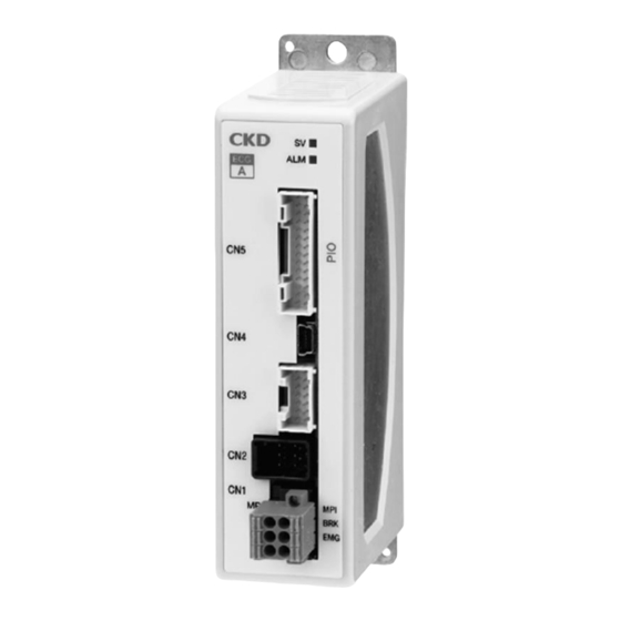
SM-A27751-A/3 1. PRODUCT OVERVIEW 1.3 Names of Parts SV: Servo lamp A or B: Controller identification ALM: Alarm lamp CN5: Interface connector CN4: USB connector CN3: Encoder connector CN2: Motor connector CN1: Power supply connector Code Name Description [If there is no alarm]Indicates whether servo is ON or OFF Servo ON: Steady green Servo OFF: Blinking green (lit once per second) Servo lamp... -
Page 14: Model Number Indication
SM-A27751-A/3 1. PRODUCT OVERVIEW 1.4 Model Number Indication *C: The I/O cable length can only be selected when the interface specification is I/O specification. In a case other than the I/O specification, 00 only. ◼ ECG-A Series ◼ ECG-B Series 2021-11-18... -
Page 15: Specifications
SM-A27751-A/3 1. PRODUCT OVERVIEW 1.5 Specifications Basic specifications ◼ ECG-A Series Items Descriptions Applicable actuators EBS-G/EBR-G Setting tool Setting software (S-Tools) 64-point mode, simple 7-point mode, solenoid valve mode double 2 position type, Operation mode (PIO) solenoid valve mode double 3 position type, solenoid valve mode single type Number of inputs 13 points Number of outputs... - Page 16 SM-A27751-A/3 1. PRODUCT OVERVIEW ◼ ECG-B Series Items Descriptions Applicable actuators FLSH-G/FLCR-G/FGRC-G Setting tool Setting software (S-Tools) 64-point mode, simple 7-point mode, solenoid valve mode double 2 position type, Operation mode (PIO) solenoid valve mode double 3 position type, solenoid valve mode single type Number of inputs 13 points Number of outputs...
-
Page 17: Dimensions
SM-A27751-A/3 1. PRODUCT OVERVIEW 1.6 Dimensions For the external dimensions of controllers with other specifications than parallel I/O specifications, refer to the instruction manual for each interface specification. ECG-A (Parallel I/O specifications) ◼ Normal mount ◼ DIN rail mount Grounding terminal (M3 ... -
Page 18: Ecg-B (Parallel I/O Specifications)
SM-A27751-A/3 1. PRODUCT OVERVIEW ECG-B (Parallel I/O specifications) ◼ Normal mount ◼ DIN rail mount Grounding terminal (M3 5 pan head screw) 2021-11-18... -
Page 19: Installation
SM-A27751-A/3 2. INSTALLATION 2. INSTALLATION DANGER Do not use the product in a place where dangerous substances such as ignitable, inflammable, or explosive materials are present. Ignition, inflammation, or explosion may occur. Prevent water and oil from splashing onto the product. A fire, electric leakage, or failure may occur. - Page 20 SM-A27751-A/3 2. INSTALLATION WARNING Do not install the product on combustibles. Fire may result if the product is installed directly on or near combustibles. Design a safety circuit or device to prevent damage to the equipment or an accident resulting in injury or death when the machine stops due to an emergency stop, power failure, or other system abnormalities.
- Page 21 SM-A27751-A/3 2. INSTALLATION CAUTION The wiring must be so arranged that no inductive noise is applied. • Avoid locations where large currents or strong magnetic fields are generated. • Do not use the same piping and wiring (by using a multi core cable) as other large motor power cables.
-
Page 22: Installation Precautions
SM-A27751-A/3 2. INSTALLATION 2.1 Installation precautions ⚫ Confirm the ambient temperature and atmosphere listed in the product specifications when storing or using the product. ⚫ Install the product away from direct sunlight, heat generating sources, dust, corrosive gas, explosive gas, combustible gas, and combustibles in general. The product was not designed to be chemically resistant. -
Page 23: Connection
SM-A27751-A/3 2. INSTALLATION 2.3 Connection WARNING Perform the wiring with the power supply turned OFF. Touching the electrical wiring connections (bare charger) may cause electric shock. Do not touch the charger with bare hands. Doing so may cause electric shock. Read and fully understand this instruction manual before performing the electrical wiring. -
Page 24: Power Supply Wiring
SM-A27751-A/3 2. INSTALLATION Power supply wiring ◼ Power supply connector specifications WARNING Always set the input for force brake release (BRK) to either 0 VDC or open during normal operation, so that the brake can be applied. If 24 VDC is applied to force brake release (BRK), the brake will be forcibly released, and the movable part of the actuator could fall, causing injury or damaging the workpiece. - Page 25 SM-A27751-A/3 2. INSTALLATION ◼ Specifications of power supply circuit ECG-A Series Item Specifications Motor power supply voltage 24 VDC ±10% □35(EBS-04,EBR-04) 2.4 A or less Motor section instantaneous max. □42(EBS-05,EBR-05) 2.7 A or less current □35(EBS-08,EBR-08) 4.0 A or less Control power supply voltage 24 VDC ±10% Current consumption...
- Page 26 SM-A27751-A/3 2. INSTALLATION ◼ Basic power supply configuration WARNING Always set the input for force brake release (BRK) to either 0 VDC or open during normal operation, so that the brake can be applied. If 24 VDC is applied to force brake release (BRK), the brake will be forcibly released, and the movable part of the actuator could fall, causing injury or damaging the workpiece.
-
Page 27: Actuator Wiring
SM-A27751-A/3 2. INSTALLATION Actuator wiring Use the dedicated relay cables to wire the controller and actuator. The combinations of controller and relay cable are shown in the table below. Controller Relay cable Motor cable EA-CBLM2-*** Note1 ECG-A Series Encoder cable EA-CBLE2-*** Note1 ECG-B Series Motor and encoder relay cable... - Page 28 SM-A27751-A/3 2. INSTALLATION ◼ Motor cable Model number explanation (ECG-A Series): P4 Series ◼ Motor cable dimensions (ECG-A Series): P4 Series Controller side Actuator side 2021-11-18...
- Page 29 SM-A27751-A/3 2. INSTALLATION ◼ Encoder cable Model number explanation (ECG-A Series):Standard Series ◼ Encoder cable dimensions (ECG-A Series):Standard Series Actuator side Controller side 2021-11-18...
- Page 30 SM-A27751-A/3 2. INSTALLATION ◼ Encoder cable Model number explanation (ECG-A Series):P4 Series ◼ Encoder cable dimensions (ECG-A Series):P4 Series Actuator side Controller side 2021-11-18...
- Page 31 SM-A27751-A/3 2. INSTALLATION ◼ Motor and encoder relay cable Model number explanation (ECG-B Series) ◼ Motor and encoder relay External dimensions (ECG-B Series) Actuator side Controller side 2021-11-18...
-
Page 32: I/O Cable Wiring
SM-A27751-A/3 2. INSTALLATION I/O cable wiring Use the dedicated I/O cable to wire the controller and upper system (PLC). The I/O cables and signal assignments are used for both the ECG-A Series and the ECG-B Series. ◼ I/O cable Model number explanation ◼... - Page 33 SM-A27751-A/3 2. INSTALLATION ◼ I/O cable wiring diagram CAUTION Reconfirm wiring prior to passing current to prevent mis wiring. After turning the power ON, use the setting tool to confirm that the input/output signals are correct. External power 24 VDC Note 2 supply Input common +/-Note 3...
- Page 34 SM-A27751-A/3 2. INSTALLATION ◼ I/O cable assignment Identification Identification (insulator) (insulator) Name Name Color Mark Color Mark General purpose General purpose Orange Red, 1 dash Orange Black, 1 dash input 12 output 12 General purpose General purpose Gray Red, 1 dash Gray Black, 1 dash input 11...
- Page 35 SM-A27751-A/3 2. INSTALLATION ◼ General purpose input/output signal assignment Signal name list The table below lists the input and output signals. Refer to “3.4.6 Positioning operation” for details of operations. <Input signals> Abbrevi- Signal name Explanation ation Point number selection PSBn Sets the point number (0 to 63) to be selected when the movement start, in binary (n = 0 to 5).
- Page 36 SM-A27751-A/3 2. INSTALLATION <Output signals> Signal name Abbreviation Explanation Point number The number (0 to 63) of the point that has completed the movement is output in binary. (n=0 to PCBn confirmation bit n Point movement PEND Turns ON when the movement is completed. completed Point number n PnEND...
- Page 37 SM-A27751-A/3 2. INSTALLATION Operation modes and signal assignment Solenoid valve Solenoid valve Solenoid valve Simple 7-point 64-point mode mode double 2 mode double 3 mode single mode position type position type type General purpose input 0 PSB0 P1ST V1ST V1ST General purpose input 1 PSB1 P2ST...
- Page 38 SM-A27751-A/3 2. INSTALLATION ◼ Input/output circuit <Input circuit> Item Specifications Number of inputs Input voltage 24 VDC ±10% Input current 4 mA Min. ON input voltage 19 V or less Max. OFF input current 0.2 mA or less Input 0 to 12 Internal circuit Input COM...
-
Page 39: S Tools Setting Software Wiring
SM-A27751-A/3 2. INSTALLATION S Tools setting software wiring CAUTION During normal operation, remove the USB cable from the controller before use. The actuator may malfunction. ◼ Communication specifications Item Specifications Interface USB 2.0 Communication speed Full speed (12 Mbps) ◼ Connection method <Connecting>... -
Page 40: Usage
SM-A27751-A/3 3. USAGE 3. USAGE DANGER Do not enter the operating area of the device when the product is in an operational state. The product may operate unexpectedly and an injury may occur. Do not work with wet hands. An electric shock may occur. WARNING Confirm the safety of the operating range of the equipment before supplying electricity to the product. -
Page 41: Setting Actuator Information
SM-A27751-A/3 3. USAGE CAUTION Do not actuate the movable part of the actuator by external force or cause the actuator to accelerate rapidly. Regenerative current may cause malfunction or damage. At the home position return, do not bump the piston rod or table against the mechanical stopper, etc., except in the clamping operation. -
Page 42: Parameters Data Configuration
SM-A27751-A/3 3. USAGE 3.2 PARAMETERS DATA CONFIGURATION Use the S Tools setting software to set or change parameters. Refer to the S Tools setting software instruction manual (SM A11147) for specific setting instructions and other details. Parameters List Initial Name Note 1 Description Setting range Unit... - Page 43 SM-A27751-A/3 3. USAGE Initial Name Note 1 Description Setting range Unit value Set the time to spend for completing pressing in the pressing interval. Pressing judgment (During the pressing judgment time, when the 0 to 9999 time current value reaches the one corresponding to the value set in the pressing rate, it is judged that pressing is complete.) Set the current value to maintain the...
- Page 44 SM-A27751-A/3 3. USAGE Initial Name Description Setting range Unit value 64-point mode, simple 7-point mode, solenoid valve mode double Operation mode Set the operation mode. Refer to “3.4.6 64-point 2 position type, solenoid valve None Positioning operation” for details. (PIO) mode mode double 3 position type, solenoid valve mode single type...
-
Page 45: Soft Limit
SM-A27751-A/3 3. USAGE Soft limit This parameters determines the movable range in transport and pressing operations. Exceeding the soft limit range during the above operations results in an alarm output. If an operation completed in a position outside of the soft limit range, the alarm is output before starting the next operation. ◼... -
Page 46: Zone Output
SM-A27751-A/3 3. USAGE Zone output When the current position is within the setting range, output signals Zone 1 and Zone 2 can be turned ON or OFF. ◼ EBS/EBR/FLSH/FLCR E.g. Zone 1 (-): 20 mm, Zone 1 (+): 50 mm, Zone hysteresis: 5 mm (Sample settings) Zone 2 (-): 50 mm, Zone 2 (+): 20 mm, Zone hysteresis: 5 mm (Sample settings) Zone 1 (+) Zone 1 (-) - Page 47 SM-A27751-A/3 3. USAGE If the zone setting value is 360 or more or -360 or less, the setting value is treated as 0. ゾーン1(+) Zone 1 (+) Zone 1 (-) ゾーン1(-) Zone output ゾーン出力 ON range ON範囲 Setting example Zone 1 (+) ... 9999.99 [deg] Zone 1 (-) ...
-
Page 48: Adjusting The Gains
SM-A27751-A/3 3. USAGE Adjusting the gains In the following cases, change the setting of the parameters “G1 gain (responsiveness)” and “G2 gain (load magnification).” For the change of the gains, the setting software S-Tools is required. For more information, including how to set these settings, refer to “Adjustment” in “3.7.2 Control Panel” of S-Tools Instruction Manual (SM-A11147). - Page 49 SM-A27751-A/3 3. USAGE <EBR series (Standard Series)> 24 VDC / Actuator model number 24 VDC / Vertical Horizontal Note 1 Motor Series Size mounting Screw lead direction Note 1: The actuator eigenvalue to be applied by setting “0” is the parameter at the power supply voltage of 24 VDC and horizontal installation.
- Page 50 SM-A27751-A/3 3. USAGE ◼ Setting of gains by power supply voltage and installation method (P4 Series) When installing the EBS series and EBR series actuators vertically, change the setting of the parameters “G1 gain (responsiveness)” and “G2 gain (load magnification)” according to the table below. <EBS series (P4 Series)>...
- Page 51 SM-A27751-A/3 3. USAGE <EBR series (P4 Series)> 24 VDC / Actuator model number 24 VDC / Vertical Horizontal Note 1 Motor Series Size mounting Screw lead direction Note 1: The actuator eigenvalue to be applied by setting “0” is the parameter at the power supply voltage of 24 VDC and horizontal installation.
- Page 52 SM-A27751-A/3 3. USAGE ◼ Gain adjustment method If there is abnormality in the operation of the actuator, adjust the gain by the following methods. If abnormal sound is generated during a stop If high-pitched abnormal sound is generated from the actuator during a stop, the set value of the gain is high, so decrease the G2 gain.
-
Page 53: Point Data Configuration
SM-A27751-A/3 3. USAGE 3.3 POINT DATA CONFIGURATION Use the S-Tools setting software to set or change the point data. Refer to the S-Tools setting software instruction manual (SM-A11147) for specific setting instructions and other details. Positioning point The number of point data that can be set depends on the operation mode. The operation mode can be selected via parameters. -
Page 54: Point Data List
SM-A27751-A/3 3. USAGE Point data list The following items can be set for each point. Setting item Description Select either Absolute or Incremental. Position specification Refer to “3.3.3 Selecting the position specification method” for details. method Select Positioning operation, Pressing operation 1, or Pressing operation 2. Operation method Refer to “3.3.4 Selecting the operation method”... -
Page 55: Selecting The Position Specification Method
SM-A27751-A/3 3. USAGE Selecting the position specification method You can select either Absolute or Incremental as the position specification method. ・Setting range and initial values (factory-default) Actuator model Initial value of position Position specification selection specification Series EBS/EBR/FLSH/ Absolute Absolute FLCR/FGRC Incremental Note 1... -
Page 56: Selecting The Operation Method
SM-A27751-A/3 3. USAGE Selecting the operation method As operation method, you can select from Positioning operation, Pressing operation 1, and Pressing operation 2. ・Setting range and initial values (factory default) Actuator model Initial value of Operation selection operation Series Positioning operation EBS/EBR/FLSH/ Pressing operation 1 Note 1 Note 2... -
Page 57: Setting The Position
SM-A27751-A/3 3. USAGE Setting the position Set the movement position. The movement position differs depending on the position specification method and operation method. ・Setting range and initial values (factory-default) Actuator model Position setting range Initial position value [mm], [deg] Note 1 [mm], [deg] Note 1 Series EBS/EBR/FLSH/... -
Page 58: Setting The Positioning Width
SM-A27751-A/3 3. USAGE Setting the positioning width Set the output range for the Point travel complete output signal and Switch 1, 2 output signal. Set this using the width to the travel complete position (one side). The meaning of positioning width differs depending on the operation method. ・Setting range and initial values (factory-default) Actuator model Position width setting range... -
Page 59: Setting The Speed
SM-A27751-A/3 3. USAGE Setting the speed The speed for the travel interval can be set. ・Setting range and initial values (factory-default) <EBS/EBR series (Standard Series)> Speed setting Actuator model number Initial speed value range [mm/s] Motor mounting [mm/s] Series Body size Screw lead Note 3 direction... - Page 60 SM-A27751-A/3 3. USAGE <EBS/EBR series (P4 Series)> Speed setting Actuator model number Initial speed value range [mm/s] Motor mounting [mm/s] Series Body size Screw lead Note 3 direction Note 1, Note 2 7 to 260 15 to 400 7 to 200 GR, GD, GL 15 to 320 2 to 100...
- Page 61 SM-A27751-A/3 3. USAGE <FLSH/FLCR/FGRC series> Actuator model number Speed setting range Initial speed value [mm/s], [deg/s] [mm/s], [deg/s] Series Body size Screw lead Note 1, Note 2, Note 4 Note 3, Note 4 5 to 50 FLSH 5 to 50 5 to 50 2 to 100 10 to 250...
-
Page 62: Setting The Acceleration
SM-A27751-A/3 3. USAGE Setting the acceleration The acceleration for the travel interval can be set. ・Setting range and initial values (factory-default) Initial acceleration Actuator model Acceleration setting range value [G] Note 1 Note 2 Series [G] Note 3 EBS/EBR 0.01 to 0.70 0.00 FLSH 0.10 to 0.30... -
Page 63: Selecting The Acceleration/Deceleration Method
SM-A27751-A/3 3. USAGE Selecting the acceleration/deceleration method You can select the acceleration/deceleration method for the positioning operation and pressing operation. You can select either Common or Trapezoid as the acceleration/deceleration method. ・Selectable acceleration/deceleration methods and initial values (factory-default) Acceleration/deceleration Description method The acceleration/deceleration method set by the common Common... -
Page 64: Selecting The Rotation Direction
SM-A27751-A/3 3. USAGE Selecting the rotation direction Set the rotation direction of the FGRC. ・Selectable rotation directions Rotation Description direction The rotation direction set in the common rotation direction of the parameter Common data is applied. Close rotation From the current position to the target position, it rotates to a direction in Note 1, Note 2 which the operation distance is short. -
Page 65: Setting The Gain Magnification
Note 1 When this is set to 0, gain magnification will not be used. Note 2 Gain magnification is not used because the initial value (factory-default) is set to 0. Using the wrong setting could result in unstable control. If control is unstable, contact CKD. Setting the point zone The point zone output signal can be set as the distance from the home position, where the boundary value for switching the signal from OFF to ON and ON to OFF is a point zone (−) and (+), respectively,... -
Page 66: Setting The Pressing Rate
SM-A27751-A/3 3. USAGE Setting the pressing rate The rate to the maximum pressing force in a pressing interval can be set. ・Setting range and initial values (factory-default) Actuator model number Setting range of the Default value of pressing pressing rate rate Screw Series... -
Page 67: Setting The Pressing Speed
SM-A27751-A/3 3. USAGE Setting the pressing speed The speed of the pushing interval can be set. ・Setting range and initial values (factory default) Initial pressing speed Actuator model number Pressing speed setting range value [mm/s], [deg/s] [mm/s], [deg/s] Note 1 Note 3 Series Note 2 Note 3 EBS/EBR/FLSH/... -
Page 68: Operation
SM-A27751-A/3 3. USAGE 3.4 OPERATION For the upper device to recognize a general purpose input signal (PIO input signal), it is necessary to continue inputting the signal for a period of time longer than the period set by the “input signal filter” of parameter. Emergency stop and release CAUTION Be careful of emergency stop wiring disconnection. -
Page 69: Force Brake Release
SM-A27751-A/3 3. USAGE Force brake release WARNING Always set the input for force brake release (BRK) to either 0 VDC or open during normal operation, so that the brake can be applied. If 24 VDC is applied to force brake release (BRK), the brake will be forcibly released. The movable part of the actuator could fall, causing injury or damaging the workpiece. -
Page 70: Servo On/Off
SM-A27751-A/3 3. USAGE Servo ON/OFF WARNING Confirm safety within the operation range. Turning the servo OFF during operation could result in unexpected operation. CAUTION When turning the servo ON, check that the actuator operates safely. The actuator could start operating once the servo is turned ON, which could cause injury or damage the workpiece. -
Page 71: From Power-On To Home Position Return
SM-A27751-A/3 3. USAGE From power-on to home position return CAUTION Do not change the power supply voltage after turning on the power. The actuator may not operate normally when executing the travel. The diagram below shows the timing of home position return completion from the beginning of the return after the power is turned on. -
Page 72: Home Position Return Operation
SM-A27751-A/3 3. USAGE Home position return operation ◼ EBS / EBR (Incremental encoder) Home position return operation is performed according to related parameters. Motor mechanical end モータ側メカエンド Home position return Home position return 原点復帰方向 原点復帰方向 direction “Normal” direction “Opposite” "標準" "反対"... - Page 73 SM-A27751-A/3 3. USAGE •Time chart Horizontal axis: Time Home position return start Displacement Home position Mechanical end Home position return complete Output signal Operation preparation complete Home position Home position return complete return start * The home position return complete output turns OFF during the home position return. 2021-11-18...
- Page 74 SM-A27751-A/3 3. USAGE ◼ EBS/EBR (Absolute encoder) Home position return operation is performed according to related parameters. Motor mechanical end モータ側メカエンド Home position return Home position return 原点復帰方向 原点復帰方向 direction “Opposite” direction “Normal” "標準" "反対" Stroke ストローク Home position offset amount 原点オフセット量...
- Page 75 SM-A27751-A/3 3. USAGE •Time chart Horizontal axis: Time Home position return start Displacement Home position Home position return complete Output signal Operation preparation complete Home position Home position return complete return start * The home position return complete output turns OFF during the home position return. 2021-11-18...
- Page 76 SM-A27751-A/3 3. USAGE ◼ FLSH Home position return operation is performed according to related parameters. The open direction of the finger is the standard home position return direction. Finger open direction Finger close direction フィンガ開方向 フィンガ閉方向 原点復帰方向 原点復帰方向 Home position return Home position return direction “Normal”...
- Page 77 SM-A27751-A/3 3. USAGE Time chart Horizontal axis: Time Home position return start Displacement Home position Mechanical end Home position return complete Output signal Operation preparation complete Home position Home position return start return complete * The home position return complete output turns OFF during the home position return. 2021-11-18...
- Page 78 SM-A27751-A/3 3. USAGE ◼ FLCR Home position return operation is performed according to related parameters. Mechanical end on PULL side PULL側メカエンド Home position return Home position return 原点復帰方向 原点復帰方向 direction “Normal” direction “Opposite” "標準" "反対" Stroke ストローク Home position 原点オフセット量 offset amount Home position 原点...
- Page 79 SM-A27751-A/3 3. USAGE Time chart Horizontal axis: Time 横軸:時間 Home position 原点復帰開始 return start Displacement 変位 Home position 原点 Mechanical end メカエンド Home position 原点復帰完了 return complete Output signal 出力信号 Operation preparation 運転準備完了 complete Home position 原点復帰 Home position 原点復帰 return start return complete 開始...
- Page 80 SM-A27751-A/3 3. USAGE ◼ FGRC Home position return operation is performed according to related parameters. *This is a figure seen from the upper surface of the table. Home position offset Proximity sensor detection range (1) When the command of a home position return is given, an operation is started in the specified rotation direction.
- Page 81 SM-A27751-A/3 3. USAGE Time chart Horizontal axis: Time 横軸:時間 Home position 原点復帰開始 return start Displacement 変位 Home position 原点 近接センサ検出範囲 Proximity sensor detection range Home position 原点復帰完了 return complete Output 出力信号 signal Operation 運転準備完了 preparation complete Home position 原点復帰 原点復帰 Home position return start return complete...
-
Page 82: Positioning Operation
SM-A27751-A/3 3. USAGE Positioning operation ◼ Normal mode (64-point mode) <Point operation> Once the point number is specified with the point number selection bit, traveling begins via ON edge input of the point travel start signal. The input/output signals below are used for operations. ・Input signal 0: OFF (level input), 1: ON (level input), 1↑: ON edge input General purpose... - Page 83 SM-A27751-A/3 3. USAGE ・Operation procedure Set the point number in the point number selection bit. Turn ON the point travel start Output the point number set by the point number confirmation bit and confirm that point travel completion is ON. ・Time chart Horizontal axis: Time Point travel...
- Page 84 SM-A27751-A/3 3. USAGE <Jog operation> Use the following input and output signals for operation. General General purpose input purpose input Description JOG (-) travel JOG (+) travel start start 1↑ Starts JOG operation to the opposite motor side. Stops JOG operation to the opposite motor side. 1↑...
- Page 85 SM-A27751-A/3 3. USAGE ◼ Simple 7-point mode <Point operation> Traveling begins via ON edge input of the point travel start signal. Use the following input and output signals. ・Input signal 0: OFF (level input), 1: ON (level input), 1↑: ON edge input General purpose input 0 to 6 Description...
- Page 86 SM-A27751-A/3 3. USAGE ・Time chart Horizontal axis: Time Point No. 1 travel start Point No. 2 travel start Point No. 3 travel start Point No. 4 Input signal travel start Point No. 5 travel start Point No. 6 travel start Point No.
- Page 87 SM-A27751-A/3 3. USAGE ◼ Solenoid valve mode (double 2 position type) Travels between two points via ON edge input. ・Input signal 0: OFF (level input), 1: ON (level input), 1↑: ON edge input General General purpose purpose input 0 input 1 Description Solenoid Solenoid...
- Page 88 SM-A27751-A/3 3. USAGE ・Time chart Horizontal axis: Time Solenoid valve travel command 1 Input signal Solenoid valve travel command 2 Point 2 Displacement Point 1 Point 1 travel complete Point 2 travel complete Output signal Switch 1 Switch 2 Point 1 Point 2 Point 1 travel Point 2 travel...
- Page 89 SM-A27751-A/3 3. USAGE ◼ Solenoid valve mode (double 3 position type) Travels between two points when turned ON (level input). ・Input signal 0: OFF (level input), 1: ON (level input) General General purpose purpose input 0 input 1 Description Solenoid Solenoid valve travel valve travel...
- Page 90 SM-A27751-A/3 3. USAGE ・Time chart Horizontal axis: Time Solenoid valve travel command 1 Input signal Solenoid valve travel command 2 Point 2 Displacement Point 1 Point 1 travel complete Point 2 travel complete Output signal Switch 1 Switch 2 Point 2 Stops at Point 2 Point 2 travel...
- Page 91 SM-A27751-A/3 3. USAGE ◼ Solenoid valve mode (single type) Travel between two points by turning one (1) input signal OFF (level input) or ON (level input). ・Input signal 0: OFF (level input), 1: ON (level input) General purpose input 1 Description Solenoid valve travel command...
- Page 92 SM-A27751-A/3 3. USAGE ・Time chart Horizontal axis: Time Solenoid Input signal valve travel command 1 Point 2 Displacement Point 1 Point 1 travel complete Point 2 travel complete Output signal Switch 1 Switch 2 Point 2 travel Point 1 Point 2 Point 1 travel complete travel start...
-
Page 93: Other Output Signals
SM-A27751-A/3 3. USAGE Other output signals In addition to the output signals described previously, the following signals are also output. ・Output signal Output signal name Description Turns ON when within the range set with point zone (+) and point zone (-). Point zone Refer to “3.3.14 Setting the point zone”... -
Page 94: Pressing Operation
SM-A27751-A/3 3. USAGE Pressing operation Pressing operations can be performed by configuring either “pressing operation 1” or “pressing operation 2” in point data. After the travel operation, the actuator operates in the pressing interval at the set “pressing rate” or less. An alarm will not be output even if it stops upon contact with the workpiece. ・Pressing operation settings Setting item Description... - Page 95 SM-A27751-A/3 3. USAGE ・Time chart (Pressing operation 2) Horizontal axis: Time 横軸:時間 Pressing operation 押付け動作 complete position 完了位置 Pressing 押付け動作 operation start 開始位置 Displacement 変位 position Operation start position 動作開始位置 Set speed 搬送時の during transport 設定速度 Speed 速度 押付け速度 Pressing speed Holding current 保持電流...
-
Page 96: Operation When A New Operation Signal Is Input During Operation
SM-A27751-A/3 3. USAGE Operation when a new operation signal is input during operation CAUTION Be careful of the operation signal input timing. It may be impossible to operate as configured according to settings such as the position, speed and acceleration. If a new operation signal is input near the soft limit, an over soft limit alarm may be output. -
Page 97: Stop Signal Input
SM-A27751-A/3 3. USAGE Stop signal input Operation can be stopped by inputting a stop signal during operation. Travel complete is not output when stopped by the stop signal. ・Time chart Horizontal axis: Time Point travel start Input signal Stop (b contact) Point 2 Displacement Point 1... -
Page 98: Holding Operation After Travel Complete
SM-A27751-A/3 3. USAGE Holding operation after travel complete WARNING Prevent falling during vertical operation. When a workpiece is placed in the vertical direction, vibration or a sudden impact to the equipment could cause a load exceeding the holding force above to be applied. When placing a workpiece in the vertical direction, be sure to implement safety measures to prevent falling. -
Page 99: Maintenance And Inspection
SM-A27751-A/3 4. MAINTENANCE AND INSPECTION 4. MAINTENANCE AND INSPECTION WARNING Install the product before wiring. Failure to do so may cause electric shock. Do not work with wet hands. Doing so may cause electric shock. Do not touch the heat sink, cement resistance, and motor inside the controller. Doing so may cause electric shock or burns. -
Page 100: Troubleshooting
Other codes indicate that there is an error in the data inside. If the error reoccurs even after power cycling, contact your nearest CKD sales office or distributor. An error has been 0x2000 detected in writing... - Page 101 SM-A27751-A/3 5. TROUBLESHOOTING Alarm Alarm Alarm item Description Solution code reset Indicates that the model numbers of the Actuator Reconnect to the previously connected actuator. 0x3A00 actuator connected model Or, save the information of the actuator connected last time with the last time and actuator number information of the actuator being connected and turn the power ON...
- Page 102 If the error reoccurs even after power cycling, contact your nearest (initialization) memory data when CKD sales office or distributor. 0x7FFF changing data. When an alarm occurs, the actuator is in the servo OFF state. In case of an actuator with a brake, the brake is applied and the holding torque is applied.
-
Page 103: What To Check When Trouble Occurs
SM-A27751-A/3 5. TROUBLESHOOTING 5.2 What to Check when Trouble Occurs Check the light status on the controller. <Servo lamp (when the alarm lamp is off)> Lit green: Current passed to motor (servo ON) Blinking green: Current not passed to motor (servo OFF) <... -
Page 104: Problems, Causes, And Solutions
SM-A27751-A/3 5. TROUBLESHOOTING 5.3 Problems, Causes, and Solutions If the product does not operate as intended, check the table below for a possible solution. Problem Cause Solution The wiring is incorrect. Check the power supply wiring. The light on the body does not light up even Confirm that the wiring is neither pinched nor disconnected. - Page 105 It does not reach the The acceleration or speed Check the “acceleration” and “speed” for the point data. target takt. setting is incorrect. If you have any other questions or concerns, contact your nearest CKD sales office or distributor. 2021-11-18...
-
Page 106: Product Compliance
This product is intended to be incorporated into the customer equipment and use as a part of equipment. The CE marking affixed to the product itself indicates that CKD has declared conformity to the EMC Directive under our limited conditions. If the customer equipment incorporating this product is to be shipped to or used in the European Economic Area as a final product, it is the responsibility of the customer to confirm compliance with the EU Directives. -
Page 107: System Structures
SM-A27751-A/3 6. PRODUCT COMPLIANCE System structures ◼ Examples of preventive measure against EMC and installation (ECG-A Series) The following figure shows how to install this product (EBS-G series and EBR-G series) in compliance with European standards. A surge protector, EMI filter for power supply, and ferrite cores are required to comply with European standards. - Page 108 SM-A27751-A/3 6. PRODUCT COMPLIANCE ◼ Examples of preventive measure against EMC and installation (ECG-B Series) The following figure shows how to install this product (FLSH-G series, FLCR-G series, and FGRC-G series) in compliance with European standards. A surge protector, EMI filter for power supply, and ferrite cores are required to comply with European standards.
- Page 109 SM-A27751-A/3 6. PRODUCT COMPLIANCE ◼ Example of preventive measure against EMC (controller grounded) Standard mount type DIN rail mount type Connect the grounding wire to the tap hole (M3) of the Grounding terminal. Connect together the grounding wire to the fixing screw of the body.
-
Page 110: Warranty Provisions
If the product specified herein fails for reasons attributable to CKD within the warranty period specified below, CKD will promptly provide a replacement for the faulty product or a part thereof or repair the faulty product at one of CKD's facilities free of charge.
Need help?
Do you have a question about the ECG Series and is the answer not in the manual?
Questions and answers