SCHUNK VERO-S NSE mini 90 Assembly And Operating Manual
Quick-change pallet system
Hide thumbs
Also See for VERO-S NSE mini 90:
- Assembly and operating manual (43 pages) ,
- Assembly and operating manual (27 pages)

Related Manuals for SCHUNK VERO-S NSE mini 90


Summary of Contents for SCHUNK VERO-S NSE mini 90
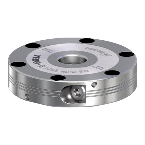
- Page 1 VERO-S quick-change pallet system NSE mini 90, NSE-M mini 90 Assembly and Operating Manual Translation of Original Operating Manual...
- Page 2 Imprint Imprint Copyright: This manual is protected by copyright. The author is SCHUNK GmbH & Co. KG. All rights reserved. Technical changes: We reserve the right to make alterations for the purpose of technical improvement. Document number: 1372754 Version: 08.00 | 04/04/2023 | en...
-
Page 3: Table Of Contents
Table of Contents Table of Contents 1 General ..................... 5 About this manual................1.1.1 Presentation of Warning Labels ............. 1.1.2 Applicable documents ..............1.1.3 Sizes..................1.2 Warranty ................... 1.3 Scope of delivery................. 1.4 Accessories ..................2 Basic safety notes ................2.1 Intended use.................. - Page 4 Table of Contents 5 Function .................... 29 5.1 Clamping functions in the pneumatically actuated clamping system ....29 5.2 Clamping functions with the manually actuated clamping system....30 5.3 Clamping slide position monitoring............31 6 Maintenance and care ................33 6.1 Ambient conditions and operating conditions ...........
-
Page 5: General
General 1 General 1.1 About this manual This manual contains important information for a safe and appropriate use of the product. This manual is an integral part of the product and must be kept accessible for the personnel at all times. Before starting work, the personnel must have read and understood this operating manual. -
Page 6: Applicable Documents
1.1.2 Applicable documents General terms of business * Catalog data sheet of the purchased product * The documents labeled with an asterisk (*) can be downloaded from schunk.com. 1.1.3 Sizes This operating manual applies to the following sizes: Quick-Change Pallet System... -
Page 7: Basic Safety Notes
Using unauthorized spare parts can endanger personnel and damage the product or cause it to malfunction. Use only original spare parts or spares authorized by SCHUNK. 08.00 | NSE mini 90, NSE-M mini 90 | VERO-S quick-change pallet system | en | 1372754... -
Page 8: Environmental And Operating Conditions
Basic safety notes 2.5 Environmental and operating conditions Required ambient conditions and operating conditions Incorrect ambient and operating conditions can make the product unsafe, leading to the risk of serious injuries, considerable material damage and/or a significant reduction to the product's life span. Make sure that the product is used only in the context of its defined application parameters, Link Technische Daten. -
Page 9: Personal Protective Equipment
Basic safety notes 2.7 Personal protective equipment Use of personal protective equipment Personal protective equipment serves to protect staff against danger which may interfere with their health or safety at work. When working on and with the product, observe the occupational health and safety regulations and wear the required personal protective equipment. -
Page 10: Transport
Basic safety notes 2.9 Transport Handling during transport Incorrect handling during transport may impair the product's safety and cause serious injuries and considerable material damage. When handling heavy weights, use lifting equipment to lift the product and transport it by appropriate means. Secure the product against falling during transportation and handling. -
Page 11: Protection During Handling And Assembly
Basic safety notes 2.12.1 Protection during handling and assembly Incorrect handling and assembly Incorrect handling and assembly may impair the product's safety and cause serious injuries and considerable material damage. Have all work carried out by appropriately qualified personnel. For all work, secure the product against accidental operation. Observe the relevant accident prevention rules. -
Page 12: Protection Against Dangerous Movements
Basic safety notes 2.12.3 Protection against dangerous movements Unexpected movements Residual energy in the system may cause serious injuries while working with the product. Switch off the energy supply, ensure that no residual energy remains and secure against inadvertent reactivation. Never rely solely on the response of the monitoring function to avert danger. - Page 13 Basic safety notes WARNING Risk of injury due to falling device, pallet or workpiece if the clamping pin is loosened erroneously or as a result of negligence. During operation, erroneous or negligent loosening of the clamping pin must be prevented using suitable countermeasures (disconnecting the power supply after locking, use of check valves or safety switches).
- Page 14 Basic safety notes CAUTION Risk of injury due to impurities (e.g. coolant or splashing water) in the exhaust and air purge connections of the clamping module or in the change interface. Cleaning the quick-change clamping system before loading. Ensure careful loading of the change interface. Take appropriate protective measures to secure the danger zone.
-
Page 15: Technical Data
If the quick-change pallet system is to be used outside the specified welding currents, please contact your SCHUNK contact person. 08.00 | NSE mini 90, NSE-M mini 90 | VERO-S quick-change pallet system | en | 1372754... -
Page 16: Assembly
Assembly 4 Assembly 4.1 Pre-assembly measures Carefully lift the product out of the packaging (e.g. with suitable lifting equipment). CAUTION Risk of injury due to sharp edges and rough or slippery surfaces Wear personal protective equipment, particularly protective gloves. Check that the delivery is complete and that there is no transport damage. - Page 17 Assembly CAUTION Risk of injury due to crushing Install the quick-change pallet system carefully. Do not place any limbs into the gaps or between the clamping station and the machine. If several linked clamping units are mounted, make sure that the flatness and height deviation of the locating surface from module to module (based on a gauge of 200 mm) lies within 0.01 mm.
-
Page 18: Fastening And Connection
Assembly Turbo connection The connection must be sealed with an O-ring in the installation space Provide ventilation Ventilation via turbo connection When dismantling the clamping system from the machine table, the corresponding openings must be secured with set-screws to prevent ingress of dirt. If several units are activated via shared hose lines, feed lines with the following minimum cross-sections must be used. - Page 19 Assembly NSE mini 90 hose-free direct connection for unlocking Air connection for "monitoring "module closed Set-screw (3x) glued, do not open! Air connection for monitoring "module open" Do not open the safety ring (3x)! Mounting hole for cylindrical screw 3x M6 hose-free direct connection, for O-rings in the turbo connection...
- Page 20 Assembly VERO-S NSE-M mini 90 Do not open the safety Actuation connection ring (2x)! turn "close" Air connection for monitoring "module closed" turn "open" Mounting hole for cylindrical screw 6x M6 for O-rings in the installation space Ventilation hole for (monitoring module open/closed) monitoring Air connection for...
- Page 21 Assembly Turbo connection Measure of clearance for PSC mini V1 fitting screw *all clamping systems of equal height within 0.01 mm Measure of clearance for IXB V1 PAL mini in the clamping pallet hose-free direct connection for unlocking connection Installation situation: partial installation Fastening and connections NSE mini 90-V1, NSE-M mini 90-V1 08.00 | NSE mini 90, NSE-M mini 90 | VERO-S quick-change pallet system | en | 1372754...
-
Page 22: Fastening And Connection Nse Mini 90
Assembly Design of the clamping pallet for position orientation that matches NSE mini 90-V1 (NSE mini 90-V1) via anti-rotation slot (for individual module) Locating groove at NSE mini 90-V1 Measure of clearance for and NSE-M mini 90-V1 IXB V1 PAL mini in the clamping pallet (interval 2 x 90°) Customer-specific pallet or device... -
Page 23: Fastening And Connection Nse-M Mini 90
VERO-S NSE mini 90-V1 quick-change pallet system (NSE-M mini 90-V1). Individual clamping pallets and clamping devices can be attached to the interface of the VERO-S NSE mini 90-V1. When producing clamping pallets in-house, pay attention to the exact positioning clearance of the indexing pin bore to the middle of the clamping pin. -
Page 24: Spa 20 Mini, Spb 20 Mini, Spc 20 Mini Clamping Bolts
This is why only screws of strength class 12.9 may be used. } 4.7 [/ 28] Only original SCHUNK clamping pins may be used. If the clamping pins are to be used in customer-owned devices, the customer must provide sufficiently dimensioned threaded holes or a sufficiently thick mounting material. - Page 25 Assembly Usage/arrangement of the different types of clamping pins Type A clamping pin, with positioning in two directions Type B clamping pin, with positioning in one direction Type C clamping pin, without positioning, with centering clearance of 0.1 mm Indexing pin for positional alignment and torque transmission with torque pin V1 und V10.
-
Page 26: Note About Pallet Changing
In this case, the system must be inspected and damaged parts must be replaced immediately. Only original SCHUNK spare parts may be used! 08.00 | NSE mini 90, NSE-M mini 90 | VERO-S quick-change pallet system | en | 1372754... -
Page 27: Pneumatic Circuit Diagram
Assembly 4.6 Pneumatic circuit diagram Pneumatic circuit Actuation with 6 bar symbols 5/3 directional control valve, center position ventilated 3/2 directional control valve Pressure switches (module open) Pressure switches (module closed) Air connection "open module" Air connection "close module" (turbo function) Pressure gauge Connection for monitoring "module open"... -
Page 28: Screw Tightening Torques
Assembly 4.7 Screw tightening torques Tightening torques for mounting clamping pins (Screw quality 12.9) Screw size Tightening torque (Nm) Tightening torques for mounting clamping modules (Screw quality ≥10.9) Schraubengröße Tightening torque (Nm) 08.00 | NSE mini 90, NSE-M mini 90 | VERO-S quick-change pallet system | en | 1372754... -
Page 29: Function
Function 5 Function The item numbers specified for the corresponding individual components relate to chapter drawings.} 9 [/ 40] 5.1 Clamping functions in the pneumatically actuated clamping system The pneumatically actuated clamping system is actuated with compressed air. An external compressed air supply is required for it to function. -
Page 30: Clamping Functions With The Manually Actuated Clamping System
Function 5.2 Clamping functions with the manually actuated clamping system The manually actuated clamping system can be operated by means of a hexagonal screwdriver (angled pin wrench). No compressed air is required for the function. This makes the clamping system extremely flexible and allows it to be used wherever no pressure medium is available. -
Page 31: Clamping Slide Position Monitoring
Function 5.3 Clamping slide position monitoring The quick-change pallet systems NSE mini 90 (-V1) and NSE-M mini 90 (-V1) have a standard pressure monitoring of the clamping slide position. This way, an electronic differential pressure switch can for instance be used to monitor the dynamic pressure at the clamping sides of the quick-change pallet system. - Page 32 Function Use of the dynamic pressure monitoring function is not mandatory for the basic operation of the clamping module. NOTICE If the pneumatic monitoring function for monitoring the clamping slide position is not used, it must be ensured that the quick-change pallet systems can be loaded or unloaded without being damaged.
-
Page 33: Maintenance And Care
If a pneumatic clamping module has to be disassembled, send the module to SCHUNK for repair. Drive ring and piston are spring preloaded and must only be removed and installed using a special installation tool by trained specialist personnel and in line with the appropriate removal and installation manual. -
Page 34: Ambient Conditions And Operating Conditions
Maintenance and care 6.1 Ambient conditions and operating conditions Make sure that the contact surfaces of the interface are always clean. Make absolutely sure that no chips of any kind can enter the interface and that the interface does not fill with cooling emulsion, which is particularly possible with vertical positioning of the clamping pin axis. -
Page 35: Troubleshooting
Check air supply } 4.3 [/ 18] Pressure below minimum Check operating pressure (min. 6 bar) A component is broken (e.g. due to Replace the module or send it to SCHUNK for overloading) repair Excess tensile load on clamping pins Reduce support weight... -
Page 36: Malfunctions In The Manually Actuated Clamping System
Incorrect direction of rotation on the Change direction of rotation on the actuating actuating screw screw A component is broken (e.g. due to Replace the module or send it to SCHUNK for overloading) repair Clamping bolt receptacle heavily soiled Clean clamping pin holder... - Page 37 Troubleshooting To operate the clamping system manually, one of these two center plugs must be dismantled. For this purpose, the safety ring (item 17) must be removed using suitable pliers. Afterwards the center plug can be removed, if necessary with the help of an M3 screw which can be screwed into the thread of the center plug (item 11).
-
Page 38: Seal Kit And Part Lists
Seal kit and part lists 8 Seal kit and part lists 8.1 Seal kit lists NSE mini 90 / NSE mini 90-V1 Sealing kit* NSE mini 90 0435117 NSE mini 90-V1 0435117 * For included items, see note X in the Parts List chapter. 8.2 Parts lists NSE mini 90 (ID 435100) / Accessory kit (ID 8508404) NSE mini 90-V1 (ID 435105) / Accessory kit (ID 8508405) - Page 39 Seal kit and part lists NSE-M mini 90 (ID 435140) NSE-M mini 90-V1 (ID 435145) Item Designation Quantity Note Base body Cover Drive ring Drive piston Setting piston Clamping slide Piston Two-part compression spring Center plug Steel ball Cylindrical pin Bearing bush Countersunk screw O-ring Ø...
-
Page 40: Drawings
Drawings 9 Drawings NSE mini 90 08.00 | NSE mini 90, NSE-M mini 90 | VERO-S quick-change pallet system | en | 1372754... - Page 41 Drawings NSE mini 90-V1 08.00 | NSE mini 90, NSE-M mini 90 | VERO-S quick-change pallet system | en | 1372754...
- Page 42 Drawings NSE-M mini 90 08.00 | NSE mini 90, NSE-M mini 90 | VERO-S quick-change pallet system | en | 1372754...
- Page 43 Drawings NSE-M mini 90-V1 08.00 | NSE mini 90, NSE-M mini 90 | VERO-S quick-change pallet system | en | 1372754...
- Page 44 H.-D. SCHUNK GmbH & Co. Spanntechnik KG Lothringer Str. 23 D-88512 Mengen Tel. +49-7572-7614-0 Fax +49-7572-7614-1099 info@de.schunk.com schunk.com Folgen Sie uns I Follow us Wir drucken nachhaltig I We print sustainable...
- Page 45 Type designation: NSA, NSE, E-compact Heinz-Dieter SCHUNK GmbH & Co. Spanntechnik KG certifies that the above-mentioned products, when used as intended and in compliance with the operating manual and the warnings on the product, are safe according to the national regulations and: −...
Need help?
Do you have a question about the VERO-S NSE mini 90 and is the answer not in the manual?
Questions and answers